Project Overview & How It Works
The Limits of Traditional Wake-on-LAN
Wake-on-LAN (WOL) is a technology for remotely powering on a PC over a network. But WOL comes with an important prerequisite.
On top of that, USB wired-LAN adapters are often labeled as WOL-capable but don't actually work in practice. This is especially true on Windows installed on Mac hardware via Boot Camp or virtualization, where WOL on the built-in or USB NIC barely works at all — driver and firmware support simply isn't there.
This Project's Approach
This project routes around WOL entirely. The key insight is that keystrokes from a USB input device — like a Logitech USB receiver — can wake a PC even from sleep. So the plan is to make the ESP32-S3 act as a USB keyboard, and when it receives an HTTP request over Wi-Fi, send a Shift keypress to wake the PC from sleep.
Parts Cost
The one part that makes this all possible is the Geekble Nano ESP32-S3. It runs about $7–8 USD on Coupang (Korean marketplace), or roughly $4–5 USD on AliExpress. If you've already bought a "WOL-capable" USB NIC that just won't work, this approach is far more reliable.
Open http://esp32.local/wake in a browser
Receives the HTTP request → sends a USB HID Shift keypress
Then connect remotely via RDP, etc.
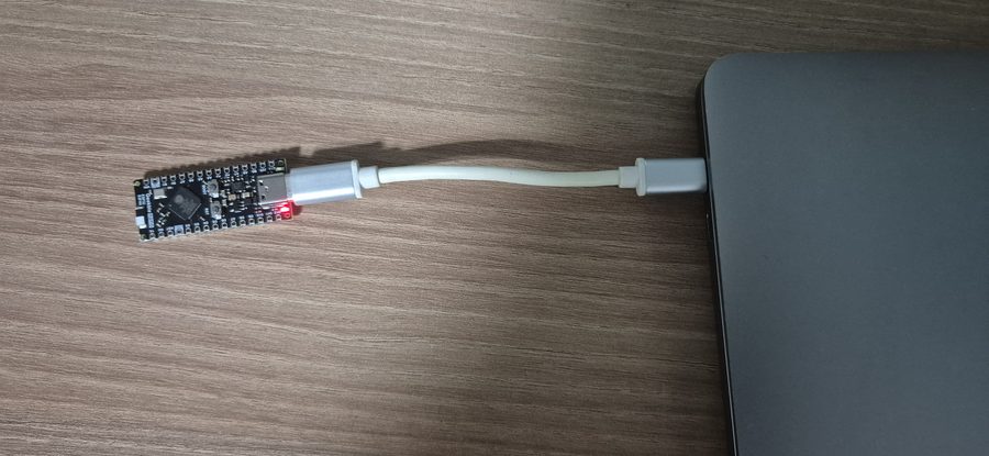
Meet the Geekble Nano ESP32-S3
The star of this project is the Geekble Nano ESP32-S3. It's an ESP32-S3 board in almost the exact same form factor as an Arduino Nano, and its hardware-level USB HID support makes it a perfect fit for this project.
Key Specs
| Item | Detail |
|---|---|
| SoC | ESP32-S3FH4R2 |
| CPU | Dual Core Xtensa LX7, 240 MHz |
| Flash | 4 MB |
| PSRAM | 2 MB |
| Connectivity | Wi-Fi 802.11 b/g/n, Bluetooth 5.0 (BLE) |
| USB | USB OTG (USB-C) — HID / CDC support |
| Size | Arduino Nano-compatible form factor |
Why the ESP32-S3?
Built-in USB HID means it can act as a keyboard or mouse without a separate USB controller (e.g. an ATmega16U2). With Wi-Fi built in as well, it single-handedly covers every requirement this project needs.
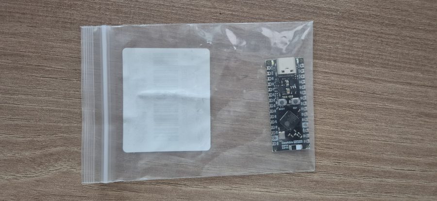
Unboxing
The package contents are simple. Open the box and all you find is the Geekble Nano board itself.

Front side
The front side has the following laid out:
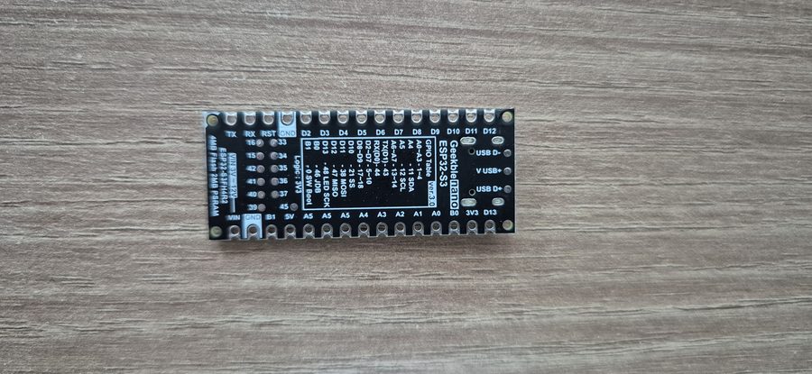
Back side
The back side has the GPIO pinout silkscreened on it, so you don't need to memorize pin numbers or dig up a datasheet. If you've used an Arduino Nano before, you can put that experience to use directly since it's the same size.
Installing Arduino IDE
The ESP32-S3 is officially supported by Arduino IDE 2.x. Download the latest version from the official site.
On Windows, just download the Windows Installer and install it like any other program.
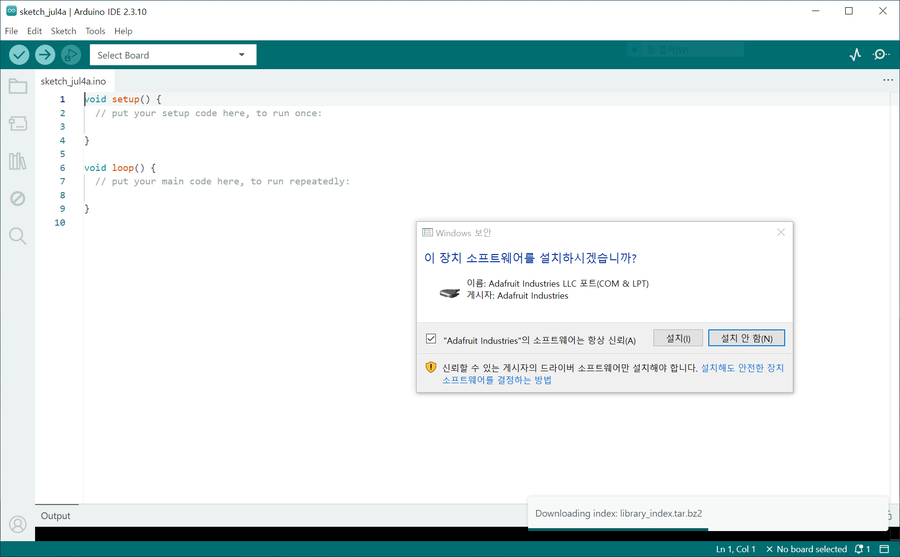
Driver installation — important!
The first time you launch Arduino IDE, a Windows driver install prompt appears. In this project, the Adafruit Industries LLC driver install prompt showed up.
Installing the ESP32 Board Package
Arduino IDE only supports AVR boards (like the Arduino Uno) out of the box. To use the ESP32-S3, you need to add Espressif's Board Package separately.
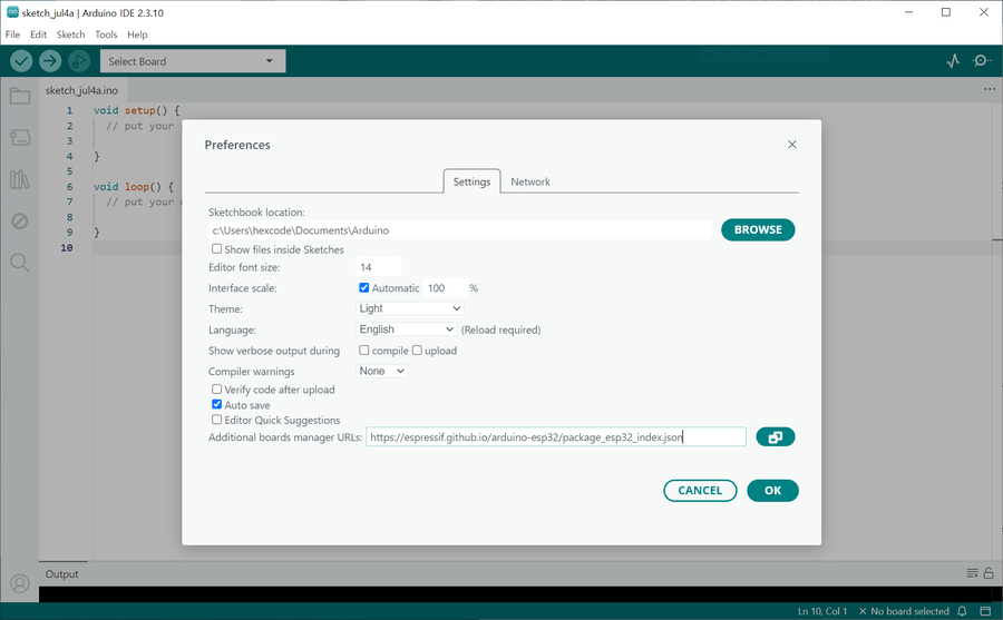
Step 1 — Add the Boards Manager URL
File → Preferences (or Ctrl+,), then
add the URL below to Additional Boards Manager URLs.
If you already have another URL there, just add this one on a new line.

Step 2 — Install the board package
Click the Boards Manager icon (the chip icon) in the left sidebar and type esp32 into the search box.
Find esp32 by Espressif Systems and click Install. Installation can take a few minutes.
Step 3 — Select the board
Select Tools → Board → ESP32 Arduino → ESP32S3 Dev Module.
The Geekble Nano doesn't have a dedicated board definition, but the ESP32S3 Dev Module setting works most reliably.

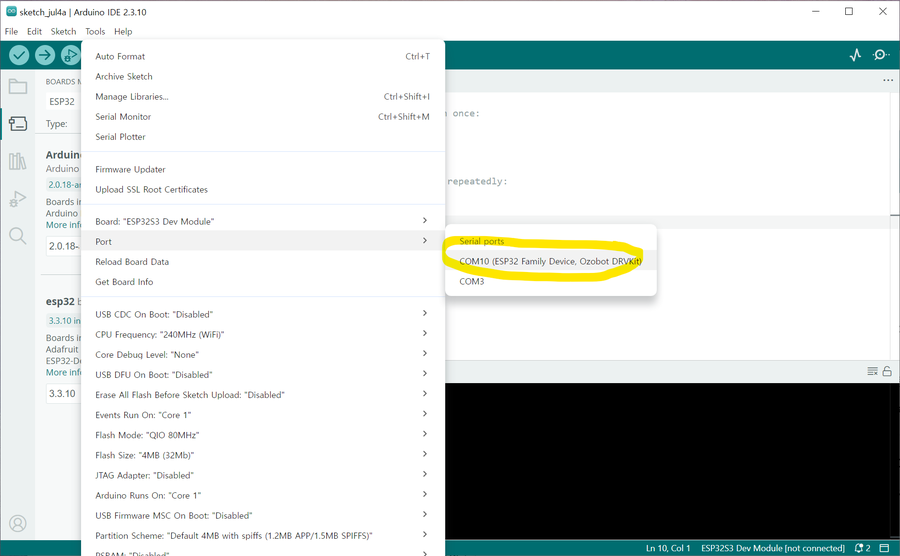
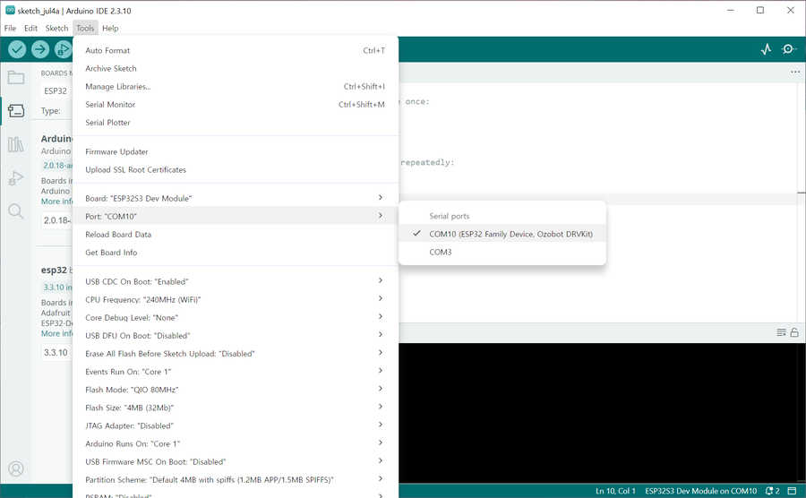
Step 4 — Select the COM port
Tools → Port, then select the newly-appeared COM port (e.g. COM10).
Blink Test — Your First Upload
Once the board is configured, the first thing to do is upload Blink. It's a trivial LED-blinking sketch, but succeeding at this step proves in one shot that the hardware, driver, board settings, and upload path are all working correctly.
The Geekble Nano's built-in LED pin
The silkscreen on the back of the Geekble Nano marks D13 = GPIO48 as the built-in LED. The default Blink example (LED_BUILTIN) may not point to the right pin, so it's safer to specify it explicitly, as in the code below.
void setup() {
pinMode(LED_PIN, OUTPUT);
}
void loop() {
digitalWrite(LED_PIN, HIGH);
delay(500);
digitalWrite(LED_PIN, LOW);
delay(500);
}
Uploading

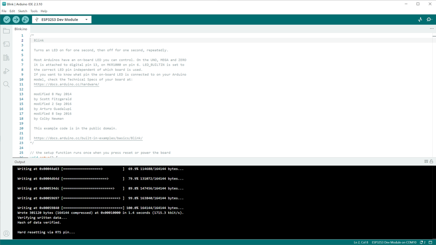
Wrote 301120 bytes ... in 1.4 secondsHash of data verified.Hard resetting via RTS pin...
If the upload fails (common on the ESP32-S3)
The ESP32-S3 sometimes needs to be put into bootloader mode manually before it will accept an upload. Try these in order.
Connecting... appears at the bottom, hold down the BOOT button → release once the upload startsMethod 2: hold BOOT → tap RST once → keep holding BOOT → click Upload
Checking the result

If the LED blinks every 0.5 seconds, you're good. This confirms that the hardware, driver, board settings, and upload path are all working correctly, and you're ready to move on to implementing USB HID.
Implementing a USB HID Keyboard
Now for the core of this project: implementing a USB HID Keyboard. The ESP32-S3 will be recognized by the PC as a USB keyboard, and code will be able to send keystrokes to it.
Step 1 — Check the USB settings
First, check the current USB-related settings in the Tools menu.

The key settings to check are:
| Item | Setting |
|---|---|
| Board | ESP32S3 Dev Module |
| USB CDC On Boot | Enabled (needs to be changed) |
| USB Mode | Hardware CDC and JTAG |
| Flash Size | 4MB |
Step 2 — USB CDC On Boot → Enabled
Change Tools → USB CDC On Boot → Enabled. This setting must be on for the USB device to initialize automatically after boot.

Starting with ESP32 Arduino Core 3.x, you can implement USB HID easily with the built-in
USB.h + USBHIDKeyboard.h libraries — no separate TinyUSB install needed.
Step 3 — Write and upload the code
Create a new sketch, paste in the code below, and upload it.
#include "USBHIDKeyboard.h"
USBHIDKeyboard Keyboard;
void setup() {
USB.begin();
Keyboard.begin();
// Wait for USB to be recognized
delay(3000);
Keyboard.println("Hello World!");
Keyboard.println("ESP32-S3 USB HID Keyboard Test");
}
void loop() {
}

Step 4 — Confirm the PC recognizes the USB keyboard
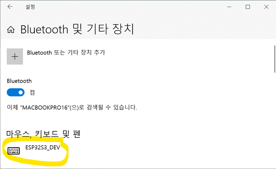
After uploading, confirm the PC recognizes the ESP32-S3 as a USB HID Keyboard device. You can check this in Windows Device Manager or via a notification.
Step 5 — Notepad typing test
Open Notepad, click into it to place the cursor, then press the ESP32's RST button once. If text types itself in after about 3 seconds, it worked.

USB.begin() → initializes the USB stackKeyboard.begin() → registers the HID keyboard devicedelay(3000) → waits for the PC to recognize the deviceKeyboard.println() → sends the keystrokes (including Enter)
This confirms the ESP32-S3 really does behave like a USB keyboard. The next step is adding Wi-Fi so this keystroke can be triggered remotely.
Connecting to Wi-Fi
With USB HID confirmed working, it's time to connect to Wi-Fi. The goal of this step is simply for the ESP32-S3 to join the router and get an IP address.
On Arduino ESP32 Core 3.x, the initialization order matters when using USB and Wi-Fi together. Verified order:
Keyboard.begin() → USB.begin() → WiFi.begin() → server.begin()
Wi-Fi connection code
const char* ssid = "YOUR_WIFI_SSID";
const char* password = "YOUR_WIFI_PASSWORD";
void setup() {
WiFi.begin(ssid, password);
while (WiFi.status() != WL_CONNECTED) {
delay(500);
}
// Connected — check the IP
// Serial.println(WiFi.localIP());
}
void loop() { }
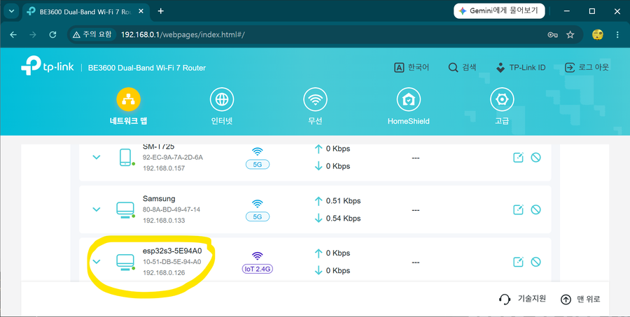
Checking the IP from the router
Once the ESP32 joins the router, it gets an IP via DHCP. Check the connected-devices list on the router's admin page, or print WiFi.localIP() to the Serial Monitor.

While running in USB HID mode, the COM port can disappear. Don't panic — recover it by holding BOOT → RST → keep holding BOOT → Upload.
Building the HTTP Web Server
With Wi-Fi confirmed working, it's time to bring up an HTTP web server. This lets a phone or remote PC's browser send an HTTP request to the ESP32.
WebServer code
#include <WebServer.h>
WebServer server(80);
void handleRoot() {
server.send(200, "text/html",
"<h1>ESP32-S3 WakeKey32</h1>"
"<p><a href='/wake'>Wake PC</a></p>"
);
}
void setup() {
// ... connect to WiFi ...
server.on("/", handleRoot);
server.begin();
}
void loop() {
server.handleClient();
}
Confirming the web server works
Opening http://[ESP32's IP address]/ in a browser shows a page served by the ESP32.

Adding
#include <ESPmDNS.h> and MDNS.begin("esp32") lets you connect via http://esp32.local/ instead of the IP address. This only works on the same Wi-Fi network.
Final Code & Stabilization Work
The combined Wi-Fi + USB HID code wasn't stable right out of the gate. It worked, but USB recognition kept dropping and the keyboard behaved erratically. Here's the process of tracking down the causes, one by one, documented as it actually happened.
Bugs found and the root cause of the instability
Calling
WiFi.setTxPower() before WiFi.begin() gets silently ignored, because the Wi-Fi driver hasn't started yet. So while I thought I was limiting output to 8.5dBm, it was actually transmitting at full power (~20dBm) the whole time. The current spike of 300mA+ during Wi-Fi transmission was colliding with USB enumeration timing — that was the root cause of the instability.
Six Stabilization Fixes
| Item | Change | Effect |
|---|---|---|
| ① setTxPower placement | Moved after WiFi.begin() |
The 8.5dBm limit now actually takes effect — the single biggest fix |
| ② USB init order | USB first → wait for tud_mounted() → then Wi-Fi |
Separates things so the Wi-Fi current spike happens after USB enumeration finishes |
| ③ CPU clock | 240MHz → 160MHz | Still plenty of performance, with more headroom for current spikes |
| ④ Wi-Fi modem sleep | WiFi.setSleep(true) |
Radio sleeps when idle → big drop in average current draw |
| ⑤ loop() delay | Added delay(2) |
Gives the CPU idle time so modem sleep can actually kick in |
| ⑥ Declare Remote Wakeup | USB.usbAttributes(...REMOTE_WAKEUP) |
Declares it in the USB descriptor → creates the Windows power-management tab |
Setting the USB Remote Wakeup descriptor
For the Power Management tab to appear in Windows Device Manager, Remote Wakeup support must be declared in the USB descriptor. This one line has to be called before USB.begin().
USB.usbAttributes(TUSB_DESC_CONFIG_ATT_SELF_POWERED | TUSB_DESC_CONFIG_ATT_REMOTE_WAKEUP);
USB.begin() doesn't mean the PC recognizes it right away. You have to wait for the PC to enumerate the USB device and match a driver. Once tud_mounted() returns true, USB is fully recognized. Turn on Wi-Fi before that check passes, and the current spike lands right in the middle of enumeration.
Final code
#include <WebServer.h>
#include <esp_system.h>
#include "USB.h"
#include "USBHIDKeyboard.h"
#include "tusb.h"
const char* ssid = "YOUR_WIFI_SSID";
const char* password = "YOUR_WIFI_PASSWORD";
WebServer server(80);
USBHIDKeyboard Keyboard;
const char* resetReasonStr() {
switch (esp_reset_reason()) {
case ESP_RST_POWERON: return "Power-on";
case ESP_RST_SW: return "Software reset";
case ESP_RST_PANIC: return "Panic (crash)";
case ESP_RST_BROWNOUT: return "BROWNOUT (power drop!)";
case ESP_RST_WDT:
case ESP_RST_INT_WDT:
case ESP_RST_TASK_WDT: return "Watchdog";
default: return "Other";
}
}
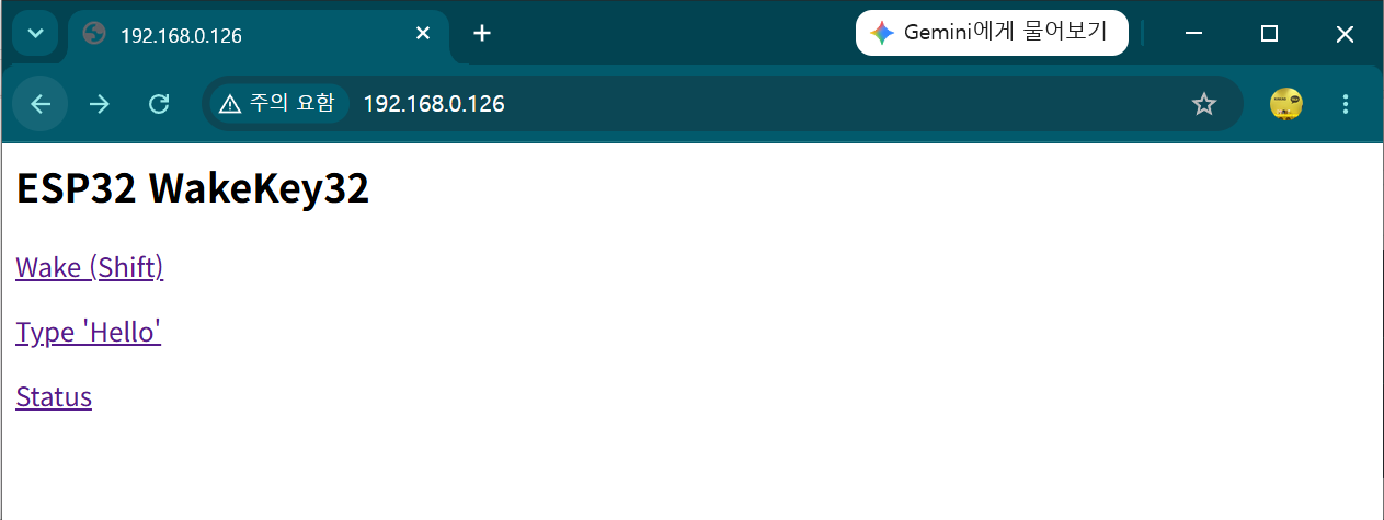
void handleRoot() {
server.send(200, "text/html",
"<h2>ESP32 WakeKey32</h2>"
"<p><a href='/wake'>Wake (Shift)</a></p>"
"<p><a href='/type?text=Hello'>Type Hello</a></p>"
"<p><a href='/status'>Status</a></p>"
);
}
void handleWake() {
if (tud_suspended()) {
tud_remote_wakeup(); // Send the USB Remote Wakeup signal
delay(1000); // Wait for the host to resume the bus
}
Keyboard.press(KEY_LEFT_SHIFT);
delay(100);
Keyboard.release(KEY_LEFT_SHIFT);
server.send(200, "text/plain", "Wake signal sent!");
}
void handleType() {
if (server.hasArg("text")) {
Keyboard.print(server.arg("text"));
server.send(200, "text/plain", "Typed: " + server.arg("text"));
} else {
server.send(400, "text/plain", "Missing ?text=");
}
}
void handleStatus() {
String msg = "WiFi : " + String(WiFi.status() == WL_CONNECTED ? "Connected" : "Disconnected") + "\n";
msg += "IP : " + WiFi.localIP().toString() + "\n";
msg += "RSSI : " + String(WiFi.RSSI()) + " dBm\n";
msg += "USB : " + String(tud_mounted() ? "Mounted" : "Not mounted") + "\n";
msg += "Reset : " + String(resetReasonStr()) + "\n";
msg += "Uptime: " + String(millis() / 1000) + " s";
server.send(200, "text/plain", msg);
}
void setup() {
setCpuFrequencyMhz(160); // 240→160MHz: more headroom for current spikes
// Declare Remote Wakeup in the USB descriptor (must be before USB.begin())
USB.usbAttributes(TUSB_DESC_CONFIG_ATT_SELF_POWERED | TUSB_DESC_CONFIG_ATT_REMOTE_WAKEUP);
Keyboard.begin();
USB.begin();
// Wait for USB enumeration to finish (up to 3s)
uint32_t t0 = millis();
while (!tud_mounted() && millis() - t0 < 3000) delay(50);
delay(500); // Extra settling time right after enumeration
WiFi.persistent(false);
WiFi.setAutoReconnect(true);
WiFi.mode(WIFI_STA);
WiFi.begin(ssid, password);
WiFi.setTxPower(WIFI_POWER_8_5dBm); // Must be called after begin() to actually apply
WiFi.setSleep(true); // Modem sleep: lowers average current draw
t0 = millis();
while (WiFi.status() != WL_CONNECTED && millis() - t0 < 15000) delay(250);
server.on("/", handleRoot);
server.on("/wake", handleWake);
server.on("/type", handleType);
server.on("/status", handleStatus);
server.begin();
}
void loop() {
server.handleClient();
delay(2); // Gives modem sleep time to actually engage
}


The /status diagnostic page
A diagnostic endpoint for checking status without a Serial connection. If USB recognition gets flaky, open http://[IP]/status.
IP : 192.168.0.xxx
RSSI : -52 dBm
USB : Mounted
Reset : Power-on
Uptime: 42 s
Switch to a rear USB port on the PC (motherboard-connected) or use a USB 3.0 port (900mA). If RSSI is worse than -75dBm, consider bumping up to
WIFI_POWER_11dBm.
Troubleshooting — Real Issues I Ran Into
Here's a rundown of the issues I actually hit while building this, and how I fixed them. If you're new to the ESP32-S3, you'll likely run into every one of these at least once.
① The COM port disappears after uploading
Once it switches into USB HID mode, Windows recognizes the ESP32 as an HID keyboard rather than a serial port, so the COM port disappears.
1. Hold down the BOOT button
2. Tap RST briefly and release
3. Release BOOT
4. Click Upload in Arduino IDE
If Serial Monitor shows
waiting for download, you've successfully entered bootloader mode. From there, Upload works even without a COM port.
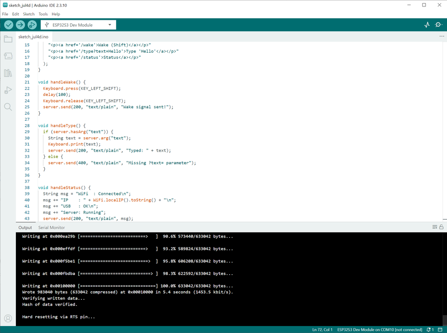
② It stops after "Hard resetting via RTS pin..."
If this message appears at the end of an upload, the upload succeeded. The ESP32 resets itself automatically and runs the new code. No action needed.
waiting for download) after this message, just press RST once to boot normally.
③ Wi-Fi keeps connecting and dropping
The ESP32's Wi-Fi radio draws a momentary current spike (up to 500mA) when it powers on. If the PC's USB port can't supply enough power, the resulting voltage drop makes the connection unstable.
1. Switch to a phone charger (5V 1A or higher) for power
2. Plug directly into the PC instead of through a USB hub
3. Add
WiFi.setTxPower(WIFI_POWER_8_5dBm) in code to lower transmit power
④ Nothing shows up in Serial Monitor
This happens when the output already scrolled by before you opened Serial Monitor. Open Serial Monitor first, then press RST to reboot — the output will start from the beginning. Also double-check the baud rate matches the code (115200).
⑤ USB HID conflicting with Serial (CDC)
With USB CDC On Boot: Enabled, calling both Serial.begin() and USB.begin() can make the port disappear or conflict.
USB CDC On Boot: Enabled is set, Serial is already wired to the USB CDC port, so there's no need to call Serial.begin() separately. Calling both Serial.begin() and USB.begin() makes two initializations fight over the same USB port, which is what causes the COM port to disappear or become unstable. Serial.print() and friends work fine over USB CDC without any separate init.
⑥ USB HID + Wi-Fi initialization order problem
Calling USB.begin() before Wi-Fi can cause the USB FreeRTOS task to interfere with Wi-Fi stack initialization, preventing Wi-Fi from connecting.
WiFi.begin() → wait for connection → server.begin() → Keyboard.begin() → USB.begin()
Live Test: Waking Windows From Sleep
A USB HID keystroke alone can't wake a sleeping PC. For a USB device to wake a PC from sleep, it has to separately send a Remote Wakeup signal over the USB bus — this is exactly why an ordinary wireless keyboard dongle is able to wake a PC from sleep.
Step 1 — Code change: add tud_remote_wakeup()
On Arduino ESP32 Core 3.x, USB.wakeupHost() doesn't exist. You have to use TinyUSB directly. Add #include "tusb.h" and send the signal with tud_remote_wakeup().
#include <WebServer.h>
#include "USB.h"
#include "USBHIDKeyboard.h"
#include "tusb.h" // added for tud_remote_wakeup()
const char* ssid = "YOUR_WIFI_SSID";
const char* password = "YOUR_WIFI_PASSWORD";
WebServer server(80);
USBHIDKeyboard Keyboard;
void handleWake() {
if (tud_suspended()) {
tud_remote_wakeup(); // Send the USB Remote Wakeup signal (the key part)
}
delay(500); // Wait for the PC to wake up
Keyboard.press(KEY_LEFT_SHIFT);
delay(100);
Keyboard.release(KEY_LEFT_SHIFT);
server.send(200, "text/plain", "Wake signal sent!");
}
void handleStatus() {
String msg = "WiFi : Connected
";
msg += "IP : " + WiFi.localIP().toString() + "
";
msg += "USB : OK
";
msg += "Suspended: ";
msg += tud_suspended() ? "Yes" : "No";
server.send(200, "text/plain", msg);
}
void setup() {
WiFi.persistent(false);
WiFi.setAutoReconnect(true);
WiFi.setTxPower(WIFI_POWER_8_5dBm);
WiFi.mode(WIFI_STA);
WiFi.begin(ssid, password);
while (WiFi.status() != WL_CONNECTED) delay(500);
server.on("/wake", handleWake);
server.on("/status", handleStatus);
server.begin();
Keyboard.begin();
USB.begin();
}
void loop() {
server.handleClient();
}
http://[IP]/status shows Suspended: Yes, USB is correctly in the suspended state. Calling /wake from there sends the Remote Wakeup signal.
Step 2 — Windows Device Manager setting
By default, Windows doesn't allow any USB device to wake the computer from sleep. You need to enable this for the ESP32 HID keyboard device ahead of time, while the PC is on.
2. Expand Human Interface Devices
3. Right-click the ESP32 HID Keyboard device → Properties
4. Power Management tab → check "Allow this device to wake the computer"
5. Click OK

Step 3 — Live test ✅
I put the Windows PC to sleep, waited a while, then called it from a different PC using one of the methods below.
① Browser address bar:
http://192.168.0.12/wake② curl (terminal/command prompt):
curl http://192.168.0.12/wake③ Clicking from the index page:
http://192.168.0.12/ → click the Wake (Shift) link
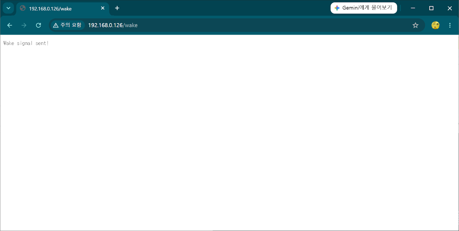
All three methods successfully woke the sleeping Windows PC. With that, this project's final goal was achieved.
Another PC / phone browser
→ HTTP request to
http://[ESP32 IP]/wake→ ESP32 sends a USB Remote Wakeup signal via
tud_remote_wakeup()→ Windows wakes from sleep
→ Then connect remotely via RDP, etc. ✅
Download the Final Code
You can download this project's finished code (.ino) and use it as-is.
ssid and password values in the code are placeholders,
YOUR_WIFI_SSID / YOUR_WIFI_PASSWORD.
Replace them with your own router's SSID and password before uploading.
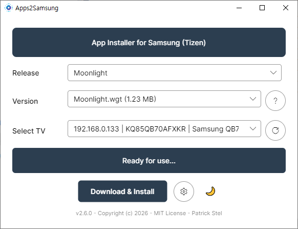
Continue Reading — Part 2
If you want to power on a desktop PC even from a full shutdown (BIOS setting included), check out Part 2, built on an AliExpress ESP32-S3 board. The code is 100% identical to this post.


댓글 없음:
댓글 쓰기