Stream Your PC Games to a Samsung TV — Sunshine + Moonlight
Cloud gaming like GeForce Now costs a monthly subscription. But what if you used your own PC's graphics card to stream high-end PC games to the big Samsung TV in your living room? All you need is Sunshine (host) on the PC and Moonlight (client) on the TV. It's free. Here's a beginner-friendly walkthrough from install to actually playing a game.
I have an 85-inch TV, and when I first bought it I tried a month-long demo of Microsoft Xbox (cloud) and GeForce Now. I was impressed that a remote cloud PC could stream to my living-room TV so I could enjoy demanding games on a huge screen without stutter. But a monthly subscription just isn't reasonable for someone who games only occasionally, so after a few tests I dropped it.
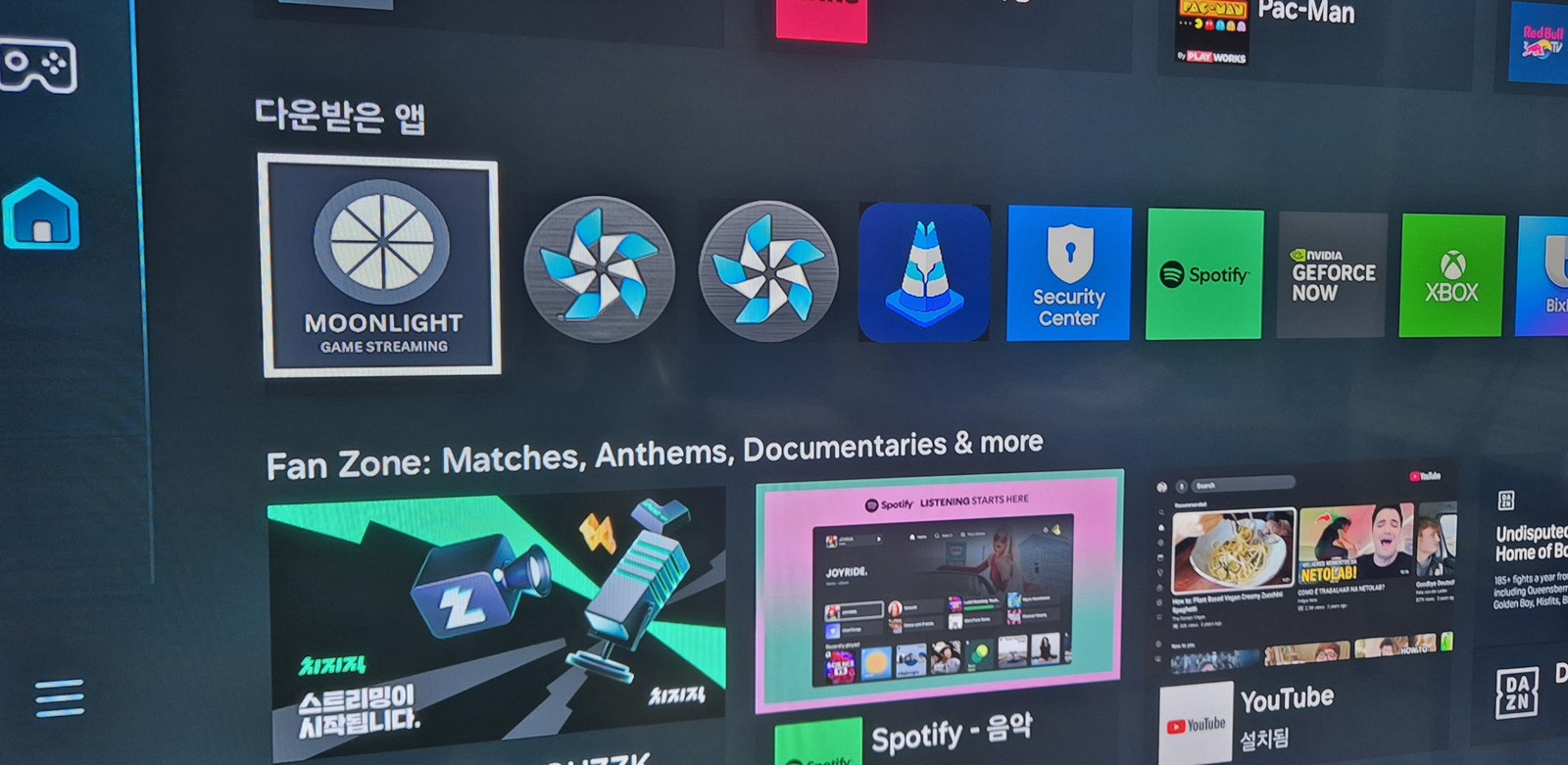
Then I heard that Samsung TVs (Tizen) support Moonlight too, and tried it right away. The principle is identical to GeForce Now, except the server is my own home PC instead of the cloud. Zero subscription cost.
First, understand the setup (it's simple)
It's not complicated. Just two programs form a pair.
🖥️ PC — Sunshine (host / sender)
│
│ streams the game video in real time over your home Wi-Fi/LAN
▼
📺 Samsung TV — Moonlight (client / receiver)
In other words, the PC actually runs the game, and the TV just receives and displays the video and sound. Your input (keyboard, mouse, gamepad) on the TV side is sent back to the PC. The TV needs no horsepower at all — the PC does all the heavy lifting.
What you need
PC (game server)
A PC with a GPU hardware encoder. NVIDIA (recommended), or a recent AMD / Intel integrated GPU also works. Windows here.
TV (receiver)
Samsung Smart TV (Tizen OS)
Network
PC and TV on the same router (same network). Wired Ethernet on the PC is recommended (Wi-Fi causes artifacts and lag).
Cost
Free (both Sunshine and Moonlight are open source)
Why NVIDIA recommended? Sunshine compresses the game video in real time using your GPU's hardware video encoder. NVIDIA (NVENC) is the most proven; recent AMD (AMF) and Intel (QuickSync) work too. A CPU alone has too much latency, so a GPU encoder is effectively required.
STEP 1 Install Moonlight on the TV (via Apps2Samsung)
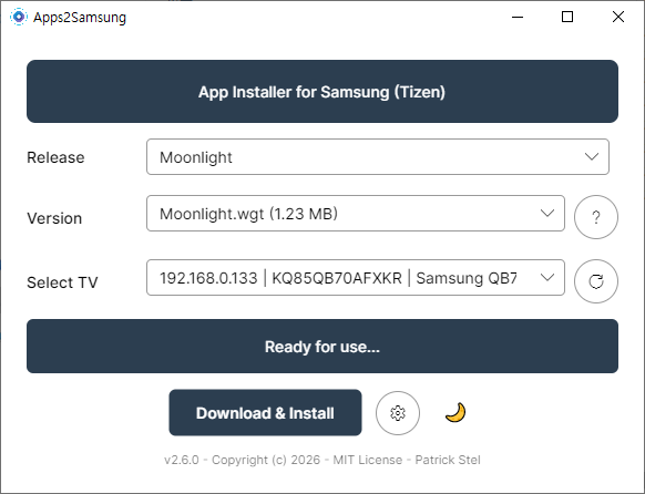
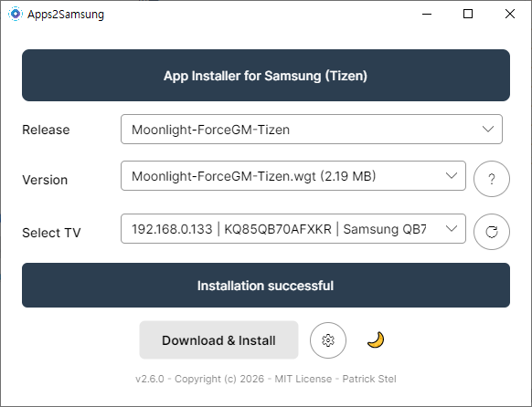
Moonlight isn't offered in Samsung's official TV app store, so you have to sideload it. Fortunately, the Apps2Samsung tool I covered previously lets you install Moonlight onto the TV from a Windows PC in just a few clicks.
📌 I've written a detailed guide on installing and using Apps2Samsung in my previous post. If you haven't done Developer Mode → Apps2Samsung install → TV connection yet, start there first.
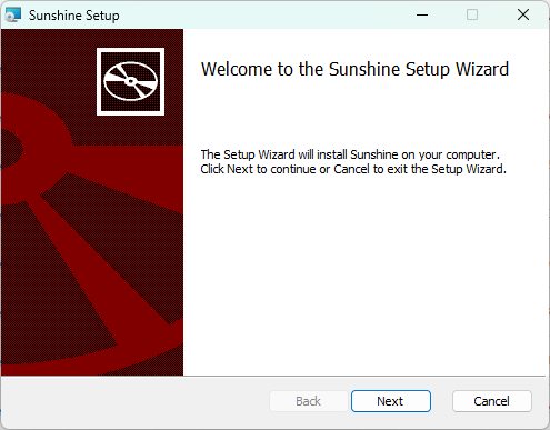
▲ The Sunshine setup wizard. Just click Next and install with the defaults.
Launched it but no window appears? (That's normal)
After installing, when you launch Sunshine a command window flashes briefly and then nothing shows up. It didn't fail to start — it's running in the background. To configure and control it, click (right-click) the Sunshine icon in the system tray at the bottom-right and choose Open Sunshine.
▲ The sun-shaped Sunshine icon in the tray (red circle) → Open Sunshine. If the tray is hidden, click the ∧ button to expand it.
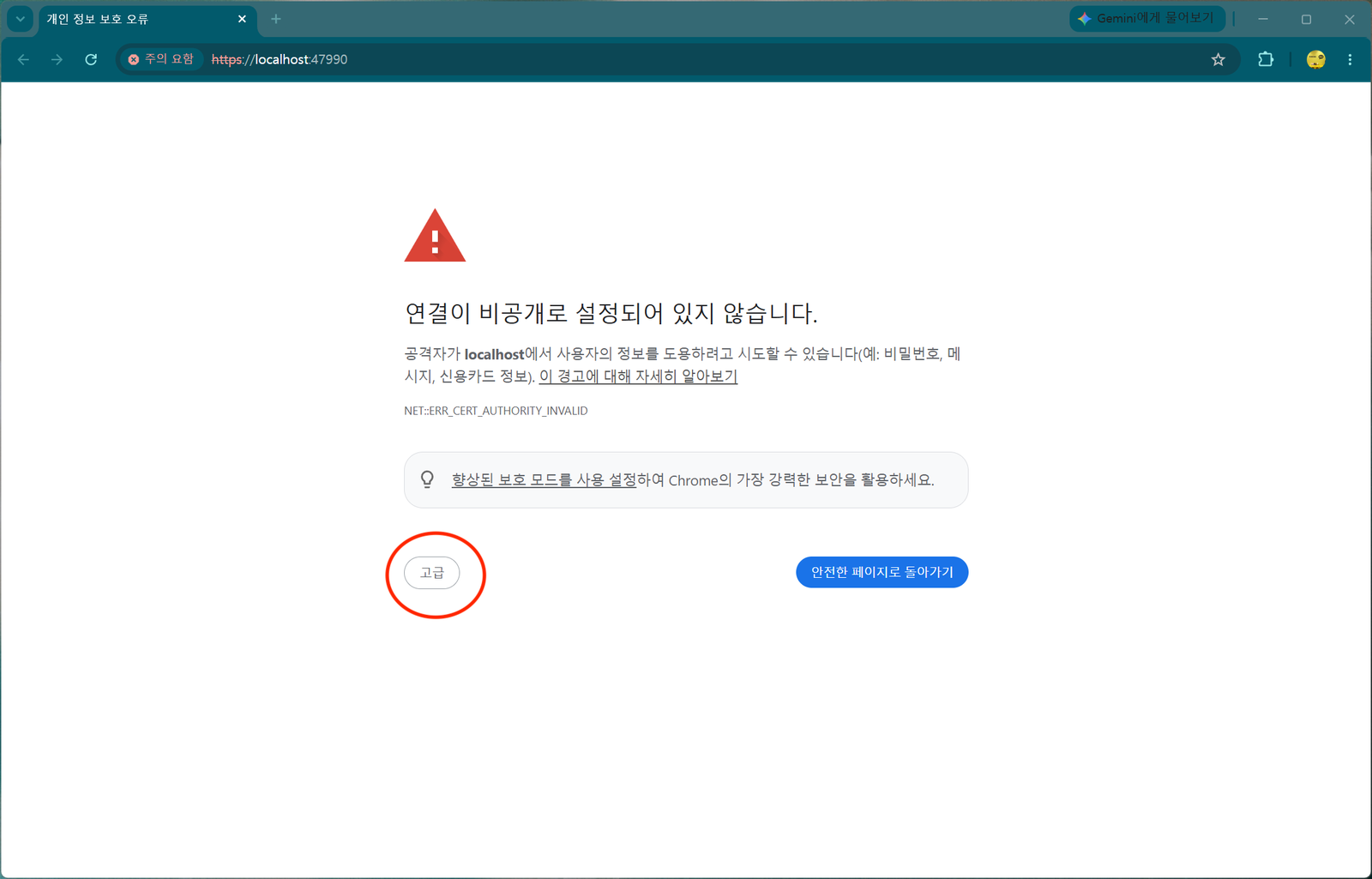
Clicking it opens the local web interface (Sunshine's control panel) in your browser. At https://localhost:47990 you'll get a certificate warning — since it's a local connection it's safe, so click [Advanced] → [Proceed] to continue.
▲ The "Your connection is not private" warning. Since you're connecting to your own PC, click [Advanced] (red circle) to proceed.
On first connect it asks you to set a password for the web interface. The default username is sunshine. It's for security; since I never connect from outside, I kept it simple. After setting the password, you're returned to the login screen — log in with it.
Install the ViGEmBus driver for gamepads
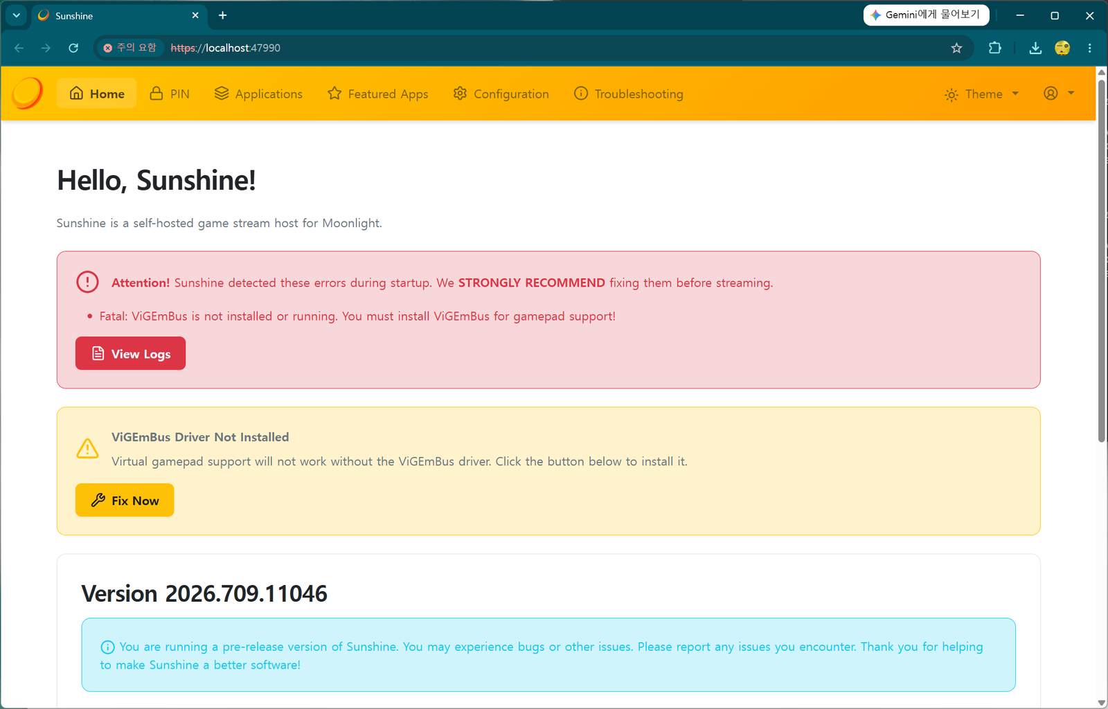
After logging in, the home screen warns that the "ViGEmBus Driver is not installed". This is the driver that emulates a virtual gamepad (controller); press Fix Now and it installs automatically.
▲ The "Fatal: ViGEmBus is not installed" warning. Click Fix Now in the yellow box to auto-install.
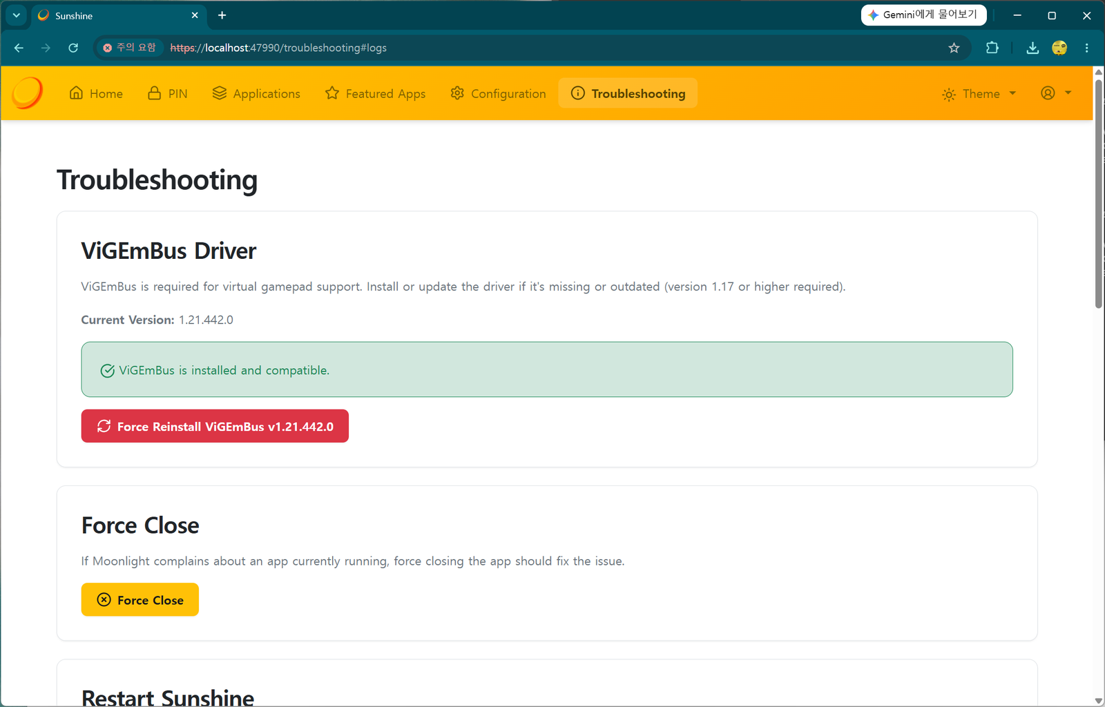
▲ The Troubleshooting screen after installing. A green "ViGEmBus is installed and compatible." means success.
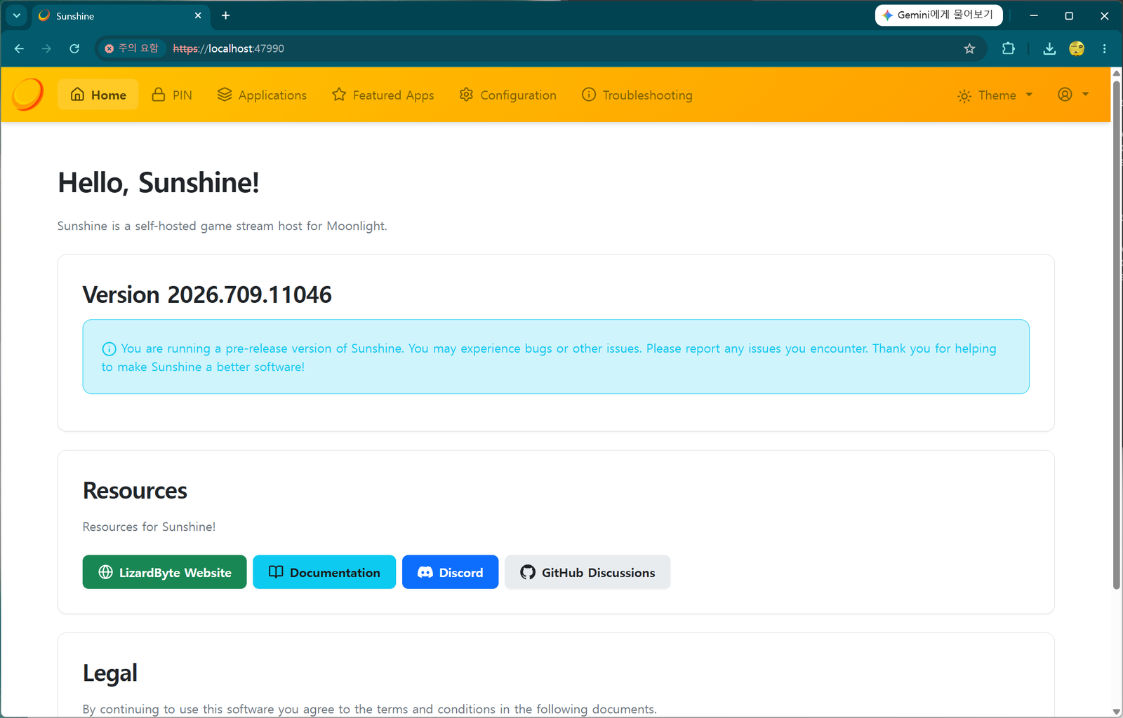
Once everything is installed and the errors are gone, you'll see a clean Sunshine home screen. The PC side is now ready.
▲ The "Hello, Sunshine!" home screen with the warnings cleared. (The pre-release note is normal.)
STEP 3 Pair the TV and PC — speed matters
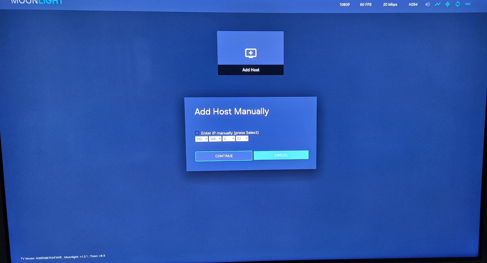
Now connect (pair) the TV and PC. Launch the Moonlight app on the TV's Apps, and under Add Host you can enter the PC's IP address.
▲ Moonlight's 'Add Host Manually'. Check "Enter IP manually," type the PC's IP (e.g. 192.168.0.x), and press CONTINUE.
How to find the PC IP: on the PC, open Command Prompt (cmd), type ipconfig, and check the "IPv4 Address." It's usually 192.168.x.x.
After entering the IP, Moonlight shows a pairing code (PIN).
▲ The PIN shown by TV Moonlight (here 4569). This number is a random example that changes every time — always read the actual code on your own screen.
Now hurry over to the PC. The window is short.
In the PC's Sunshine web interface → PIN tab, enter the pairing code shown on the TV, type a device name (e.g. SamsungTV), and press Send.
⚠️ The code 4569 in these screenshots is only an example. The pairing code is freshly generated at random every time, so it will differ — do not type 4569. Read the code currently on your TV screen and enter that. It also expires within tens of seconds, so as soon as you see the PIN on the TV, go to the PC and enter it fast. If it expires, just retry in TV Moonlight for a new code.
▲ The PIN tab in the Sunshine web UI. Enter the code (4569) and device name (SamsungTV), then Send. As the warning says, only pair devices you trust.
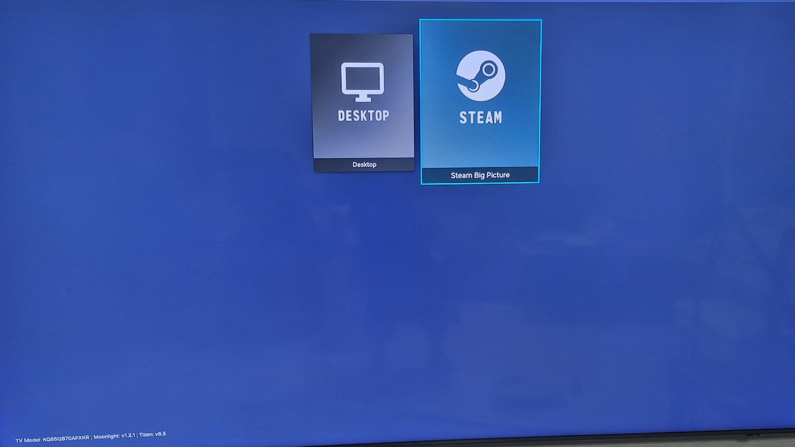
When pairing succeeds, the connected PC appears next to Add Host in Moonlight, and clicking it shows launch options like Desktop / Steam Big Picture.
▲ Pairing done. You can choose Desktop (the raw PC desktop) or Steam Big Picture (Steam's TV mode).
STEP 4 Actually play — Steam Big Picture
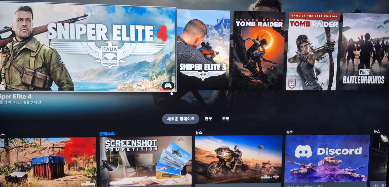
For a test, since I have Steam installed on the PC, I chose Steam Big Picture and launched a game from my Steam library.
▲ The Steam Big Picture library on the TV. Your PC's game list spreads across the big screen as-is.
Input devices (keyboard/mouse/gamepad) are a must
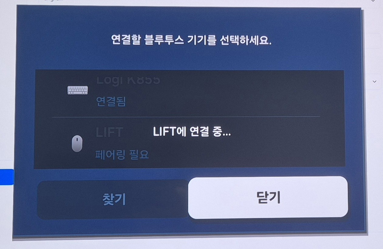
To play PC games comfortably on the TV, you need a gamepad or a keyboard/mouse connected. My Logitech keyboard and mouse (from the PC) support pairing up to 3 devices, so I connected one channel to the TV over Bluetooth.
▲ Connecting a Logitech keyboard (K855) and LIFT mouse under Samsung TV's Bluetooth device list. Multi-pairing peripherals are handy here.
As a test I ran Sniper Elite 4. Because I was on Wi-Fi, there was a little image smearing (motion blur).
▲ Sniper Elite 4 on the big TV. In sudden scenes like explosions, the Wi-Fi smearing is slightly visible.
Still, the keyboard and mouse response was fast, like on the PC, and the lag was by no means bad enough to make it unplayable. The sheer satisfaction of playing my PC games on a huge TV was more than enough.
Wrap-up — want better quality? Go wired
The appeal here is playing with your PC's full power on a big TV, with no monthly subscription. In summary:
Moonlight on the TV (receiver), Sunshine on the PC (host). Both free and open source.
On the PC: install Sunshine → ViGEmBus → PIN pairing, in that order.
If image smearing bothers you, connect the PC by wired (gigabit) Ethernet — far more stable than Wi-Fi.
For input, connect a multi-pairing keyboard/mouse or a gamepad to the TV over Bluetooth.
It's genuinely fun on a big screen, so if you have an NVIDIA PC and a Samsung TV, give it a try.
💡 You can also use it as a remote desktop, not just for games. After pairing, if you pick Desktop instead of Steam in Moonlight, your PC desktop appears on the TV. Connect a Bluetooth keyboard/mouse and you can control your PC from the couch on the big TV (web browsing, YouTube, documents, etc.) — basically a remote desktop.
※ Installing Moonlight uses Samsung's Developer Mode to sideload a community app; it's not covered by official Samsung support, and installation/use is at your own risk. Sunshine and Moonlight are open source — only play games you legitimately own.
Install Unofficial Apps on a Samsung TV with Apps2Samsung (VLC, Jellyfin & more)
The Samsung TV app store has no VLC and no Jellyfin. But with Samsung's own Developer Mode and the open-source tool Apps2Samsung, you can sideload Tizen community apps (.wgt) in just a few clicks. Here's the full walkthrough — from enabling Developer Mode to actually installing and running VLC — based on the latest interface.
Apps like Jellyfin and VLC aren't available in the Samsung TV app store, so you can't install them the normal way. But many open-source communities offer great free apps, and you can install them easily.
There's only one hurdle: putting your Samsung TV into Developer Mode. This isn't a hack — it's a feature Samsung officially built into Tizen TVs, so it's not hard. Here's how.
STEP 1 Enable Developer Mode on the TV
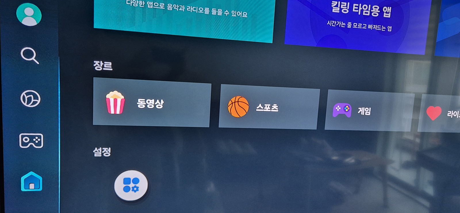
First, open the Apps screen on your TV and go to Settings.
▲ The Samsung TV Apps screen. Move to the gear-shaped Settings icon at the bottom.
On the Settings screen, press 1 2 3 4 5 in order on the remote's number keys, then press OK. The Developer Mode dialog appears.
Don't see number buttons on your newer remote?
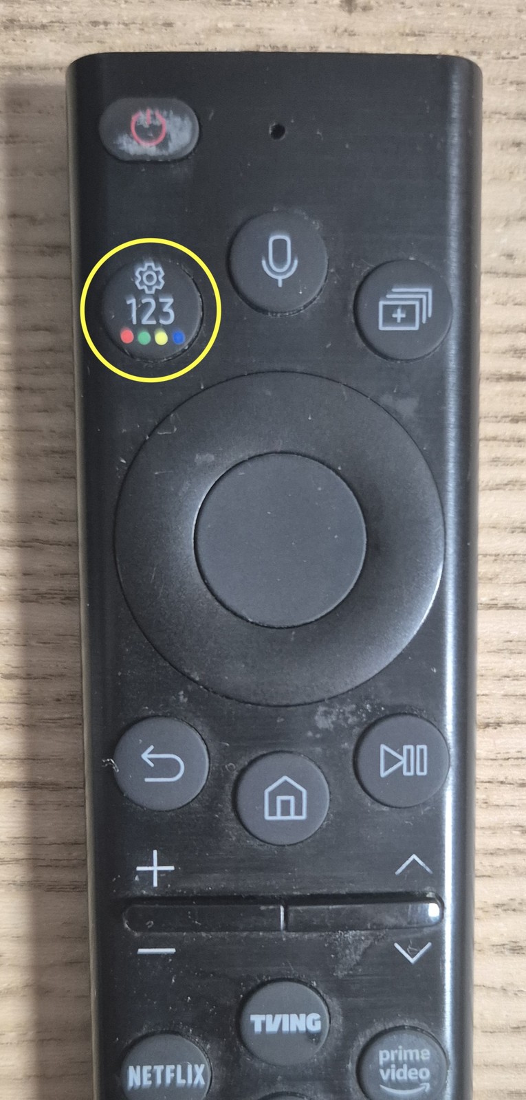
Recent Samsung Smart Remotes have no dedicated 0–9 buttons, but they do have a "123" button (yellow circle in the photo below). Press that 123 button to bring up an on-screen number pad, then use it to enter 1 2 3 4 5.
▲ The "123" button on the Samsung Smart Remote (yellow circle). Press it to pop up an on-screen number pad and enter 12345.
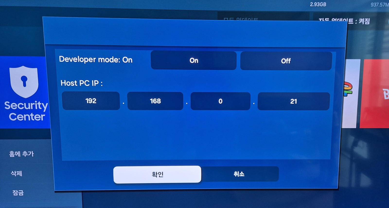
In the Developer Mode dialog, set two things:
Developer mode = On
Host PC IP — the IP address of the Windows PC that will upload and control the apps.
▲ Set Developer mode to On, enter your Windows PC's IP (example: 192.168.0.21) in Host PC IP, and confirm.
My Windows PC is 192.168.0.21, so I entered that. Use your own PC's IP. For security, apps can only be uploaded from the PC IP registered here.
How to find your Windows PC IP: open Command Prompt (cmd), type ipconfig, and look at the "IPv4 Address," or check Settings → Network & Internet. It's usually in the form 192.168.x.x.
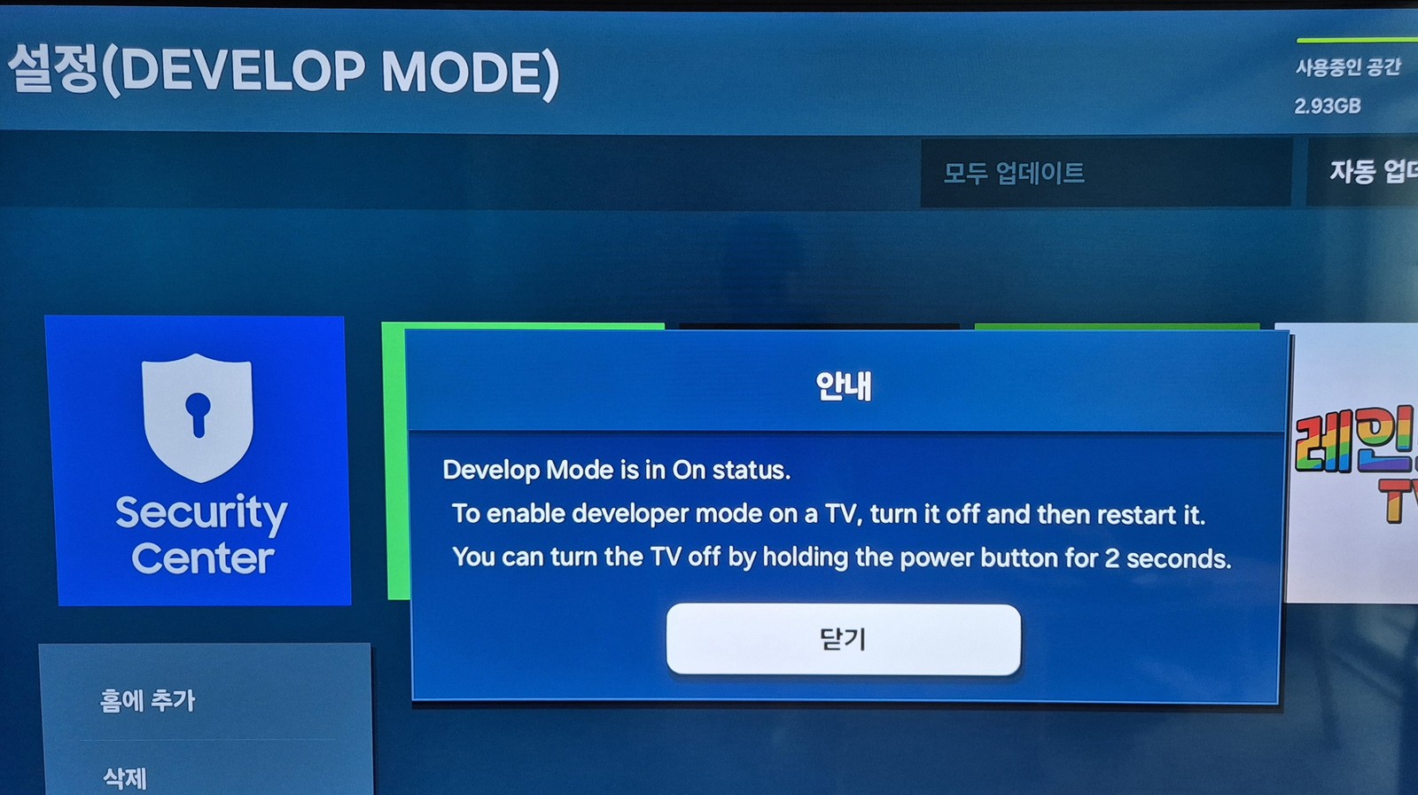
Once set, turn the TV off and fully unplug the power cable to reboot it. Developer Mode only takes effect after a restart.
▲ "Develop Mode is in On status. …turn it off and then restart it." The restart notice popup.
The on-screen message "You can turn the TV off by holding the power button for 2 seconds" means exactly that — holding the power button for 2 seconds turns the TV off. You can power it off that way, or, as I did, simply unplug the power cord and plug it back in.
STEP 2 Check the TV's IP address
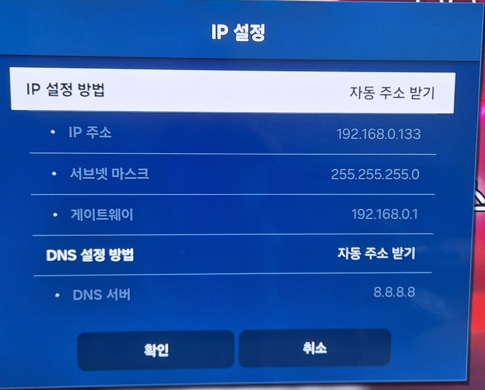
You need to know the IP of the target — that is, which IP the TV is using. Check it under Settings → Network.
▲ The TV's IP settings screen. In this example the TV IP is 192.168.0.133. You'll use this address later.
Alternatively, log into your router's admin page and check which IP the Samsung TV was assigned.
The TV and PC must be on the same network (same router). Don't mix up the Host PC IP (STEP 1) and the TV IP (STEP 2). Host PC IP = your computer; TV IP = the target TV.
STEP 3 Download and install Apps2Samsung
On your Windows PC, download the latest version of Apps2Samsung.
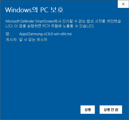
Run the downloaded .msi to install. Because it's not code-signed, Windows SmartScreen shows a warning, but it's not a harmful app — dismiss the warning and continue.
▲ The "Windows protected your PC" SmartScreen warning. Click [More info] → [Run anyway] to proceed.
The SmartScreen warning simply means the publisher is unknown, not that it's malware. Still, for peace of mind, only download from the official GitHub release above. Apps2Samsung is MIT-licensed open source, so its code is public.
STEP 4 Connect to the TV with Apps2Samsung
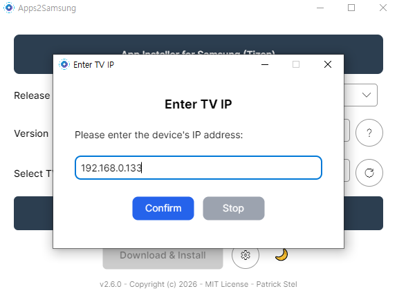
After installing, launch Apps2Samsung and it finds the TV automatically. If it doesn't, enter the TV IP manually (the address from STEP 2).
▲ In the 'Enter TV IP' window, type the TV's IP (192.168.0.133) and click Confirm.
If it can't find the TV, you'll get an error like this:
▲ "Invalid device IP or device not found." / "No devices found" error.
The usual causes are:
Developer Mode wasn't enabled properly (including forgetting to reboot).
The Host IP was set wrong in Developer Mode (wrong Windows PC IP).
The TV and PC are not on the same network.
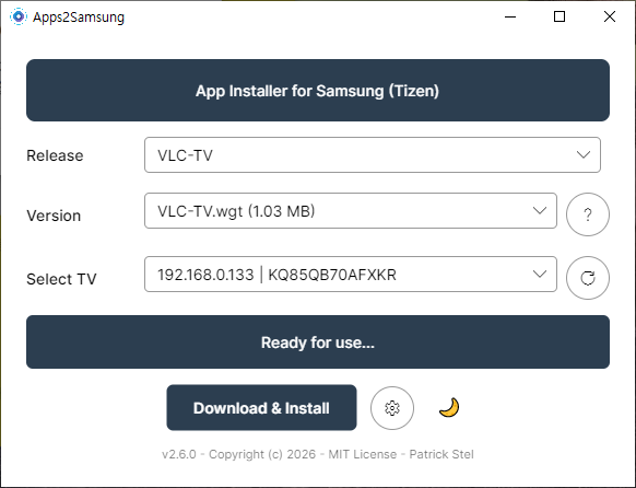
When Developer Mode is set up correctly, Apps2Samsung finds the TV right away on launch.
▲ When the TV IP and model appear under 'Select TV' and it says "Ready for use…", you're good to go.
STEP 5 Install an app — VLC as the example
Now you can install apps freely. The most useful community app is probably VLC, so as an example I installed VLC-TV. Pick the app under Release and press Download & Install.
▲ Choose VLC-TV under Release and VLC-TV.wgt under Version, and the 'Download & Install' button activates.
When installation finishes, the developer asks you to "Buy me a beer" as a donation. Feel free to support if you like — or not.
▲ "VLC-TV has been successfully installed!" The QR code is a donation link for the developer.
If installation fails
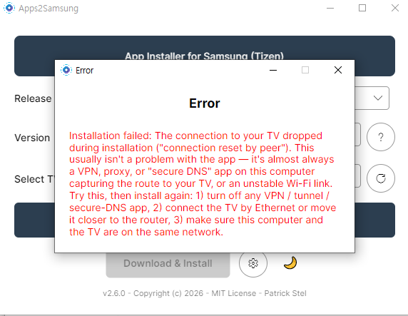
Sometimes you'll hit an error saying the connection dropped during installation:
▲ "Installation failed: The connection to your TV dropped…" This is more often a network issue than an app problem.
As the message itself notes, this is usually caused by a VPN, proxy, or "secure DNS" app on the PC hijacking the route to the TV, or an unstable Wi-Fi link. Fixes: (1) turn off any VPN/tunnel/secure-DNS app, (2) connect the TV by Ethernet or move it closer to the router, and (3) make sure the PC and TV are on the same network.
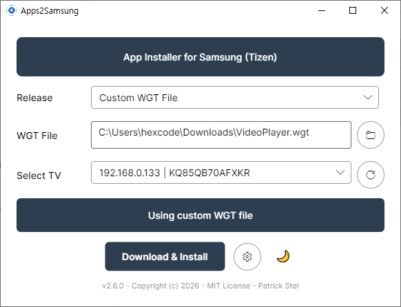
When I hit this error, I worked around it by downloading the wgt file myself and uploading it directly. In Apps2Samsung, choose Custom WGT File and point it at the downloaded .wgt file.
▲ Switch Release to 'Custom WGT File' and select the VideoPlayer.wgt you downloaded to install it.
By the way, the VideoPlayer I installed this way sounded promising by name, but turned out to be pretty limited in practice. Among community apps, VLC is the safe bet.
You can grab pre-compiled .wgt files for the Tizen community app collection here.
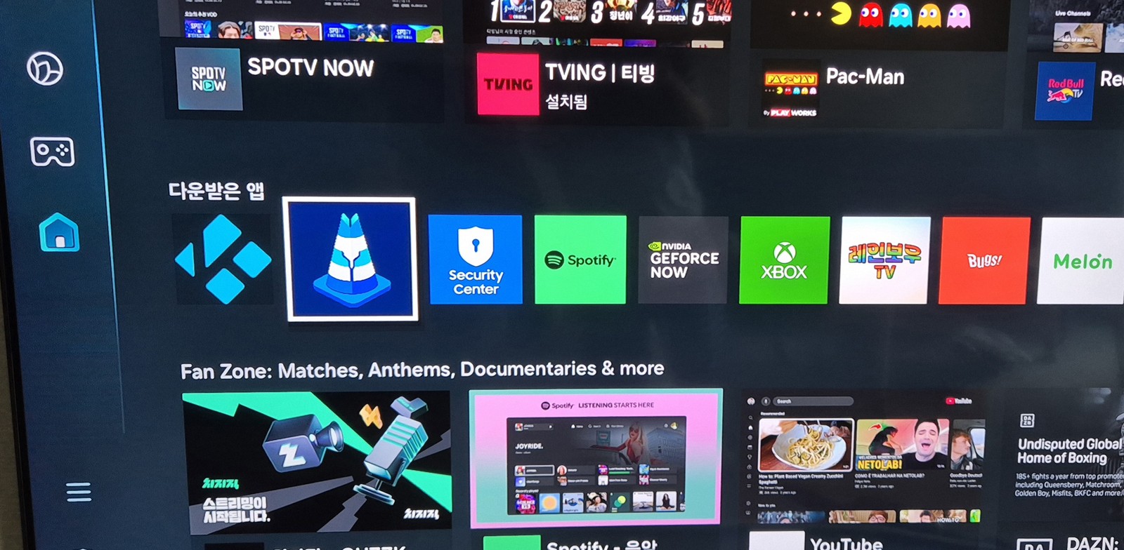
Once installed, you'll find the app in Samsung's 'Downloaded apps' list in the Apps menu.
▲ VLC (cone icon), Kodi, and other community apps sit right alongside the official apps under 'Downloaded apps'.
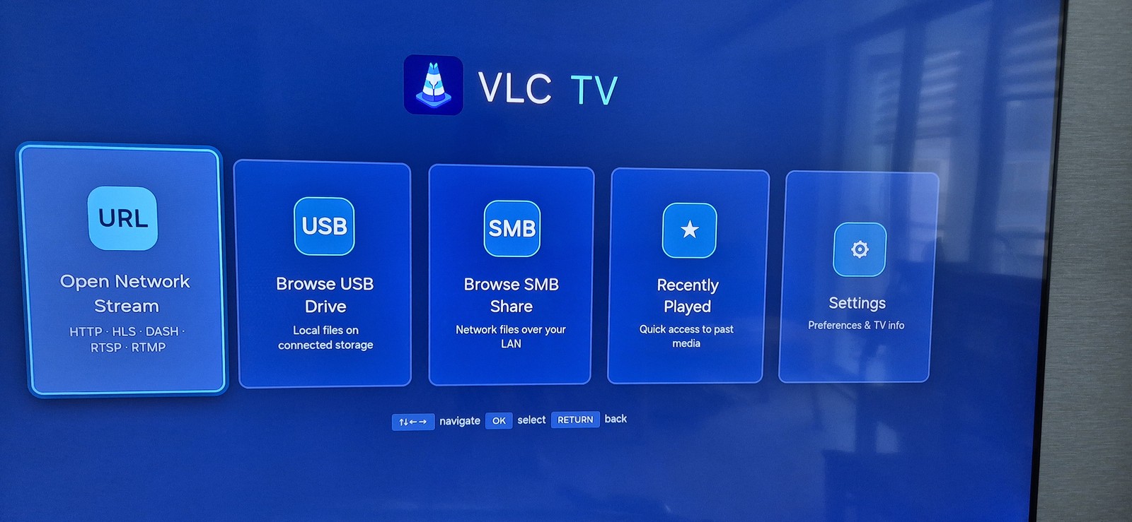
Give it a run to confirm it works. Here's VLC running on the TV:
▲ VLC TV running on a Samsung TV. It supports Open Network Stream (URL), USB, SMB shares, and Recently Played.
Wrapping up — more community apps are coming
As you can see, it's easy to sideload custom wgt apps that Samsung's store doesn't offer. Just VLC's SMB/USB playback alone dramatically boosts what a Samsung TV can do.
These days people build Tizen apps easily even through vibe coding, so I expect the community to keep releasing more free apps. For example, the vlc-tizen-tv repo was clearly vibe-coded with Claude.
※ Developer Mode is an official Samsung feature, and Apps2Samsung and the apps shown are open source. That said, community apps installed via Developer Mode are not covered by official Samsung support, and installation/use is at your own risk. Only use copyrighted content through legitimate channels.
Waking a Desktop PC From Fully Shut Down Using an AliExpress ESP32-S3 Board
Following up on Part 1 (Geekble Nano), here's how to remotely power on a desktop PC using a new ESP32-S3 dev board I picked up on AliExpress. The code is 100% identical to Part 1, but the board layout and BIOS setup are a bit different.
Part 1 covered building a USB HID Wake-on-LAN alternative with a Geekble Nano ESP32-S3.
An ESP32-S3 dev board I ordered from AliExpress arrived today, so I set up a second one specifically for my desktop PC.
Why split them by use case: when a MacBook is fully shut down, USB power gets cut entirely, so an ESP32 can only wake it from sleep.
Most desktop motherboards, on the other hand, let you power on from a full shutdown using just a keystroke, via a BIOS setting. So I've dedicated one board to the MacBook (Part 1, Geekble Nano) and a second board to the desktop (Part 2, this AliExpress board).
Possibly because it's a physically larger board, this AliExpress ESP32-S3 also felt like it held a more stable Wi-Fi connection than the mini board from Part 1.
Chapter 1
Unboxing the AliExpress ESP32-S3
I bought this on AliExpress for about $5–6 USD (7,500 KRW), with free shipping. It's cheaper than the Geekble Nano from Part 1, and physically larger too.
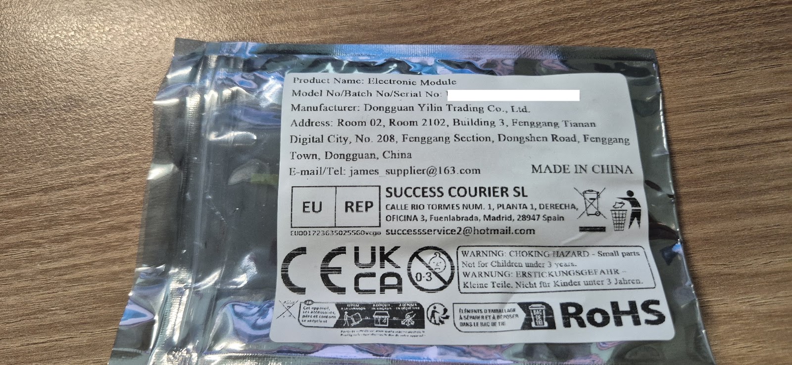
▲ The AliExpress packaging label — listed as an "Electronic Module," Made in China
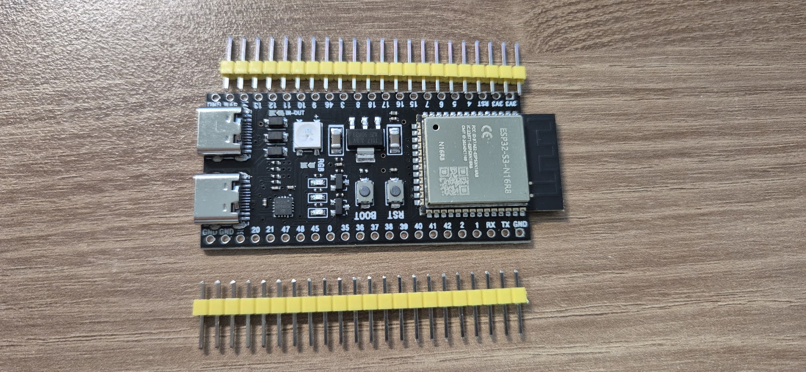
▲ Board, front side — two USB-C ports, BOOT/RST buttons, an onboard RGB LED
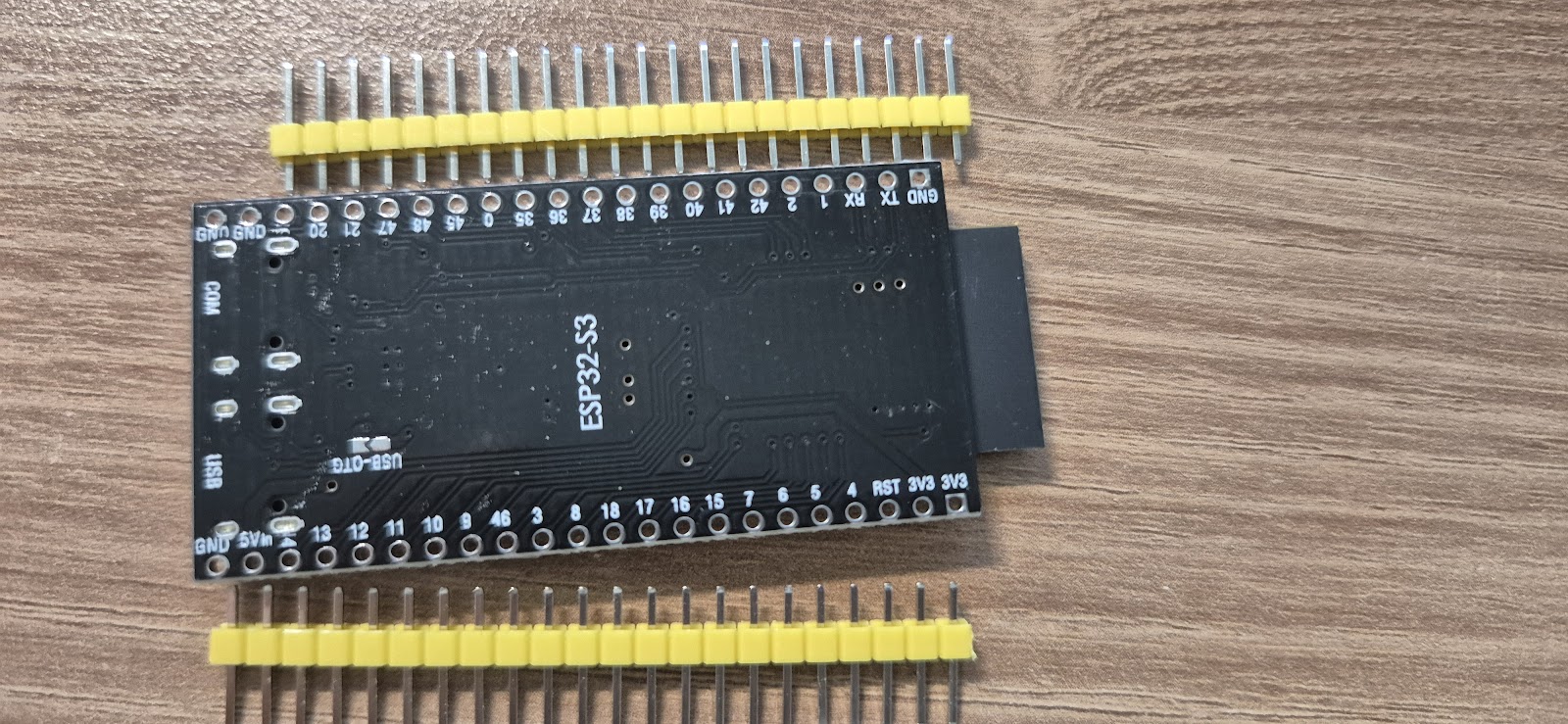
▲ Board, back side — silkscreened "ESP32-S3," with the two ports labeled USB and USB-OTG respectively
The package contents are simple — just the board itself and two rows of pin headers, no other accessories.
Chapter 2
Board Layout: Two USB Ports, Which One to Use
This board's proper module name is ESP32-S3-WROOM-1 N16R8 (16MB flash / 8MB PSRAM — more headroom than the Geekble Nano from Part 1). The wiring diagram from the AliExpress listing makes the key components easy to identify at a glance.
▲ Hardware diagram provided on the AliExpress listing page
Item
Detail
Module
ESP32-S3-WROOM-1 N16R8 (16MB Flash / 8MB PSRAM)
USB-Serial chip
CH343P
RGB LED
WS2812
Port A
USB to Serial (Type-C) — for firmware upload and Serial Monitor
Port B
ESP32-S3 Type-C USB & OTG — for acting as a USB HID keyboard
The key thing to know: this board has two USB-C ports. One goes through the CH343P chip as a "USB to Serial" port (for uploading code and debugging); the other connects directly to the ESP32-S3 chip as a "USB & OTG" port.
Just like in Part 1, you must connect to the PC through the "USB & OTG" port for it to work as a USB HID keyboard. Connecting via the Serial port won't get it recognized as a keyboard.
When uploading firmware, do the opposite: connect the Serial port (CH343P) to your PC and upload from Arduino IDE. Once the upload is done, switch the connection over to the OTG port for actual use.
Chapter 3
Setup (100% Identical to Part 1)
Installing Arduino IDE, adding the ESP32 Board Package, the USB CDC On Boot setting, implementing a USB HID Keyboard, connecting to Wi-Fi, implementing the /wake API — the entire setup process and code are completely identical to
the Part 1 post.
As long as you select the same ESP32S3 Dev Module in the Board Package screen, the code from Part 1 runs 100% as-is, with no changes needed.
Reconfirmed: as long as it's in the ESP32-S3 family, the USB HID + Wi-Fi code ports over directly regardless of manufacturer — whether it's a Geekble Nano or, as here, a generic AliExpress dev board.
What differs board to board is really just USB port placement and the GPIO pinout; the software logic stays the same.
If you haven't seen the code yet, grab it directly from the WakeKey32_final_public.ino download link at the bottom of the Part 1 post — just swap in your own Wi-Fi SSID/password and upload.
Chapter 4
Waking From Fully Shut Down: BIOS Setup
Unlike a MacBook, most desktop motherboards keep standby power flowing to USB ports even when fully shut down. So enabling "power on via USB keyboard" in the BIOS lets the ESP32's Shift keypress power the PC on from a full shutdown, not just from sleep.
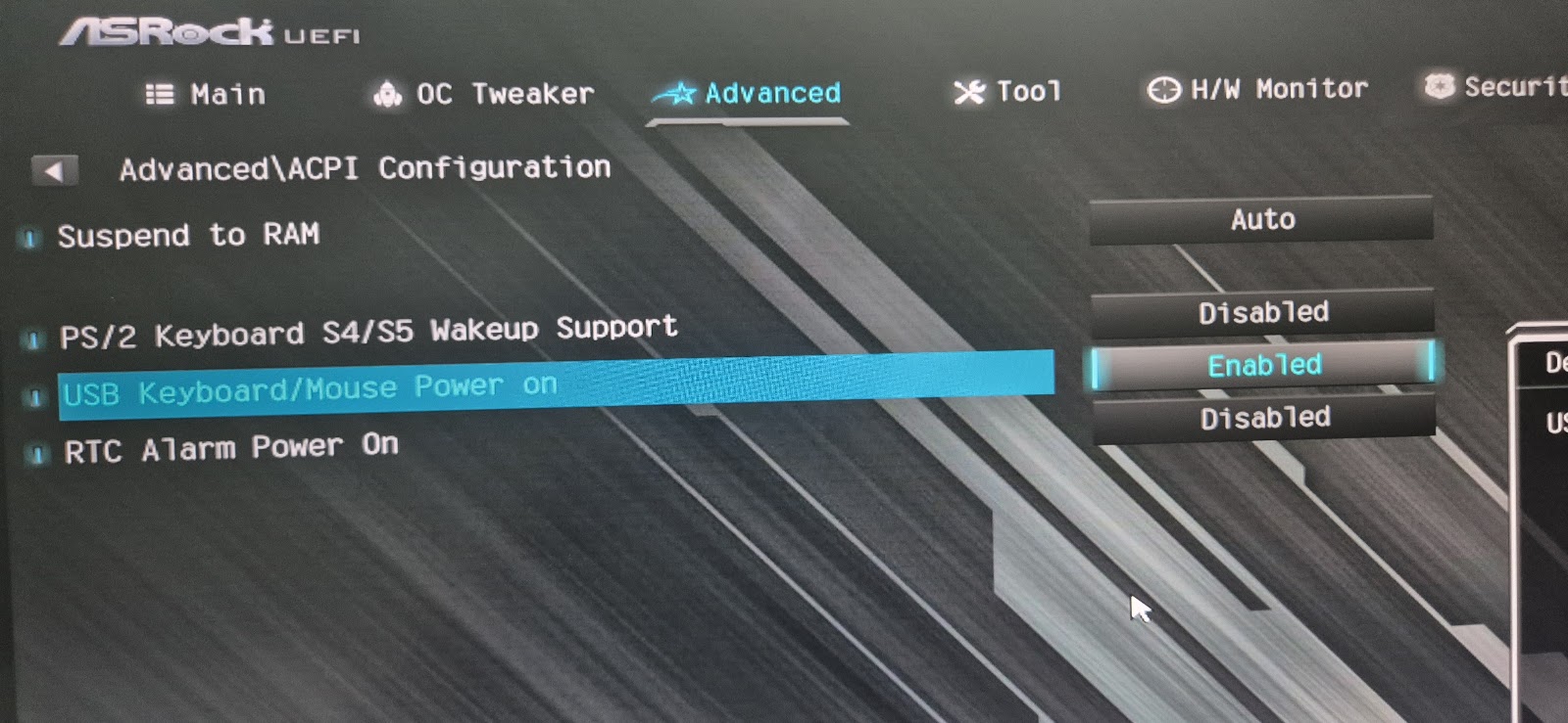
On my ASRock motherboard, the setting is found here:
Enter the UEFI setup screen → Advanced → ACPI Configuration → USB Keyboard/Mouse Power on → Enabled
▲ ASRock UEFI → Advanced → ACPI Configuration → USB Keyboard/Mouse Power on → Enabled
Menu names vary by manufacturer. ASUS, MSI, Gigabyte and others often have a similar option under a different name, like "Power On by USB Keyboard/Mouse," or it may hinge on disabling "ErP Ready."
Searching your motherboard manual for "USB Keyboard Power On" or "Wake on USB" is a good bet.
Note: on some motherboards this option only works from sleep (S3) and not from a full shutdown (S4/S5).
Even in that case, waking from sleep still works exactly as in Part 1 — so relying on sleep mode instead of a full shutdown is a reasonable fallback.
Chapter 5
Installation: Wired Directly Inside the PC Case
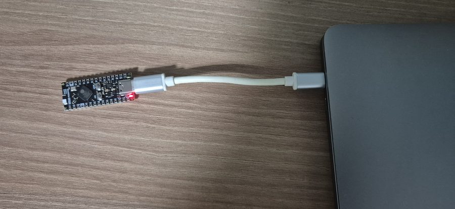
Part 1 already established that unstable power can cause current spikes during Wi-Fi transmission to drop USB recognition, so here too I wired the board directly into a motherboard USB header and left it permanently installed inside the case.
▲ Wired directly to a motherboard USB header (rear panel) for stable, always-on power
Connect it to a USB port that stays powered even with the case closed, and you can just leave it alone from then on — no maintenance needed.
Chapter 6
Real-World Results vs. Traditional WOL
After running both boards for a while, this setup has been far more reliable than traditional wired-LAN Wake-on-LAN. I tested two scenarios.
Scenario
Result
Power on from a full shutdown
Works reliably (after the BIOS setting)
Wake from sleep
Works reliably
The limits of traditional wired-LAN WOL: Magic Packets would occasionally just get dropped or silently fail, and waking from sleep in particular often just didn't happen.
On top of that, using WOL remotely requires knowing the target PC's MAC address, and delivering the Magic Packet itself is difficult unless you're on the same network — which made remote use practically infeasible.
The advantage of the ESP32 USB HID approach: no need to worry about MAC addresses or being on the same network — just send a single HTTP request to the IP of whichever PC the ESP32 is attached to (or through router port forwarding).
It's far more reliable, and the setup is far simpler too.
For now, the setup I'm happiest with is: one board dedicated to the MacBook for waking from sleep, and one board on the desktop handling both full-shutdown power-on and sleep-wake — both left permanently connected.
Wake a Sleeping PC Over Wi-Fi Building an ESP32-S3 USB HID WOL Device
A hands-on build log for waking a Windows PC that doesn't support Wake-on-LAN, by turning an ESP32-S3 into a USB keyboard and triggering it remotely over Wi-Fi.
Wake-on-LAN (WOL) is a technology for remotely powering on a PC over a network. But WOL comes with an important prerequisite.
WOL's requirement: the device sending the Magic Packet and the target PC must be on the same wired network. A router, server, NAS, or some other wired device is required. Wi-Fi alone can't reliably deliver a WOL signal.
On top of that, USB wired-LAN adapters are often labeled as WOL-capable but don't actually work in practice. This is especially true on Windows installed on Mac hardware via Boot Camp or virtualization, where WOL on the built-in or USB NIC barely works at all — driver and firmware support simply isn't there.
This Project's Approach
This project routes around WOL entirely. The key insight is that keystrokes from a USB input device — like a Logitech USB receiver — can wake a PC even from sleep. So the plan is to make the ESP32-S3 act as a USB keyboard, and when it receives an HTTP request over Wi-Fi, send a Shift keypress to wake the PC from sleep.
Why this approach works: no wired network or extra server needed — all you need is Wi-Fi. Just hit one URL from a phone or remote PC connected to the same router, and that's it.
Parts Cost
The one part that makes this all possible is the Geekble Nano ESP32-S3. It runs about $7–8 USD on Coupang (Korean marketplace), or roughly $4–5 USD on AliExpress. If you've already bought a "WOL-capable" USB NIC that just won't work, this approach is far more reliable.
📱 Phone / Remote PC Open http://esp32.local/wake in a browser
↓
Wi-Fi (local network)
↓
ESP32-S3 (Geekble Nano) Receives the HTTP request → sends a USB HID Shift keypress
↓
USB HID Keyboard (virtual)
↓
Windows PC wakes up ✓ Then connect remotely via RDP, etc.
Key point: the ESP32-S3 has built-in USB OTG, so it can implement a USB HID device (keyboard/mouse) entirely in software — no separate USB controller chip needed.
Chapter 1
Meet the Geekble Nano ESP32-S3
The star of this project is the Geekble Nano ESP32-S3. It's an ESP32-S3 board in almost the exact same form factor as an Arduino Nano, and its hardware-level USB HID support makes it a perfect fit for this project.
Key Specs
Item
Detail
SoC
ESP32-S3FH4R2
CPU
Dual Core Xtensa LX7, 240 MHz
Flash
4 MB
PSRAM
2 MB
Connectivity
Wi-Fi 802.11 b/g/n, Bluetooth 5.0 (BLE)
USB
USB OTG (USB-C) — HID / CDC support
Size
Arduino Nano-compatible form factor
Why the ESP32-S3?
Built-in USB HID
Built-in USB CDC
Built-in Wi-Fi
Bluetooth 5.0
Dual Core 240MHz
Arduino support
Arduino Nano-sized
Built-in USB HID means it can act as a keyboard or mouse without a separate USB controller (e.g. an ATmega16U2). With Wi-Fi built in as well, it single-handedly covers every requirement this project needs.
Chapter 2
Unboxing
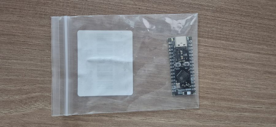
The package contents are simple. Open the box and all you find is the Geekble Nano board itself.
▲ As packaged
▲ Board, front side
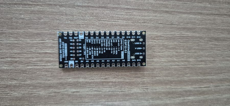
▲ Board, back side — the GPIO pinout is silkscreened right on it, which is handy
Front side
The front side has the following laid out:
USB-C port
BOOT button
RESET button
ESP32-S3FH4R2
Back side
The back side has the GPIO pinout silkscreened on it, so you don't need to memorize pin numbers or dig up a datasheet. If you've used an Arduino Nano before, you can put that experience to use directly since it's the same size.
Tip: before buying, make sure it's specifically an ESP32-S3 board. Plain ESP32 or ESP32-S2 boards may differ in USB HID support. This project specifically requires an ESP32-S3.
Chapter 3
Installing Arduino IDE
The ESP32-S3 is officially supported by Arduino IDE 2.x. Download the latest version from the official site.
https://www.arduino.cc/en/software
On Windows, just download the Windows Installer and install it like any other program.
Driver installation — important!
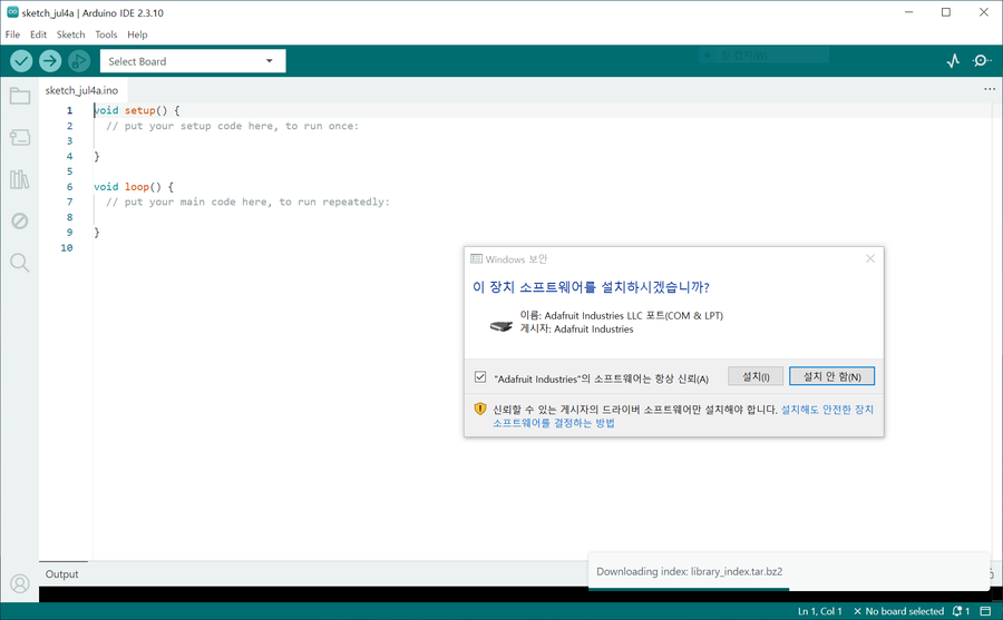
The first time you launch Arduino IDE, a Windows driver install prompt appears. In this project, the Adafruit Industries LLC driver install prompt showed up.
You must install it. Skip it and the ESP32 board may not be recognized as a port later on.
▲ The driver install screen that appears the first time you launch Arduino IDE
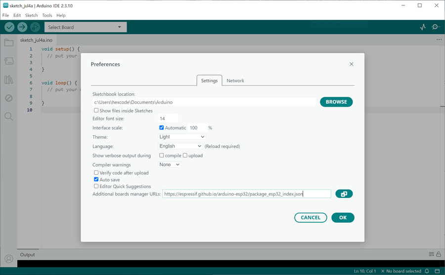
▲ The Additional Boards Manager URLs settings screen
Chapter 4
Installing the ESP32 Board Package
Arduino IDE only supports AVR boards (like the Arduino Uno) out of the box. To use the ESP32-S3, you need to add Espressif's Board Package separately.
Step 1 — Add the Boards Manager URL
File → Preferences (or Ctrl+,), then add the URL below to Additional Boards Manager URLs.
If you already have another URL there, just add this one on a new line.
▲ Search "esp32" in Boards Manager, then install esp32 by Espressif Systems
Step 2 — Install the board package
Click the Boards Manager icon (the chip icon) in the left sidebar and type esp32 into the search box.
Find esp32 by Espressif Systems and click Install. Installation can take a few minutes.
Version tip: unless you have a specific reason not to, just install the latest stable version. No need to restart the IDE afterward.
Step 3 — Select the board
Select Tools → Board → ESP32 Arduino → ESP32S3 Dev Module.
The Geekble Nano doesn't have a dedicated board definition, but the ESP32S3 Dev Module setting works most reliably.
▲ Tools → Board → selecting ESP32S3 Dev Module
Step 4 — Select the COM port
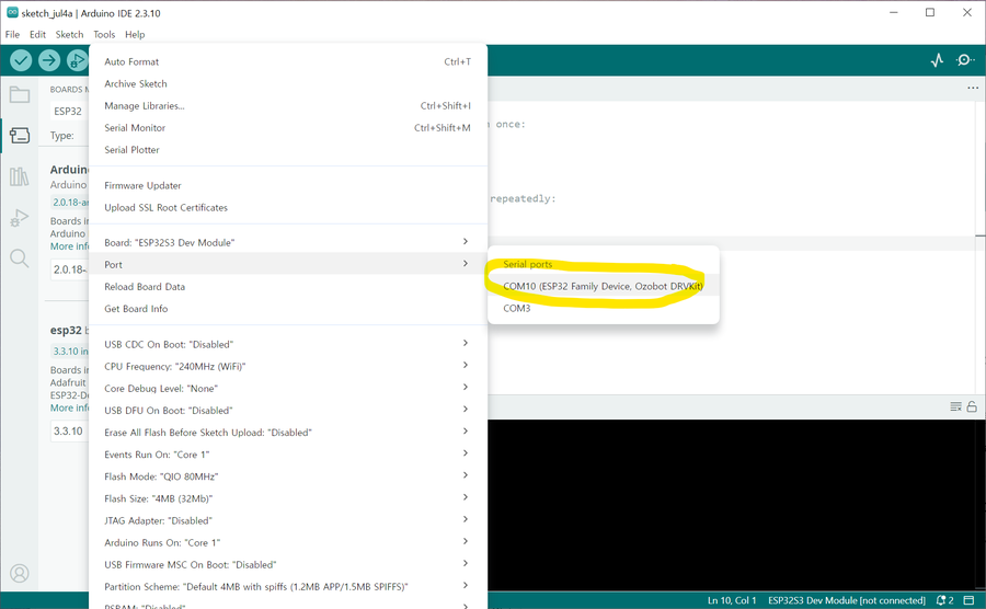
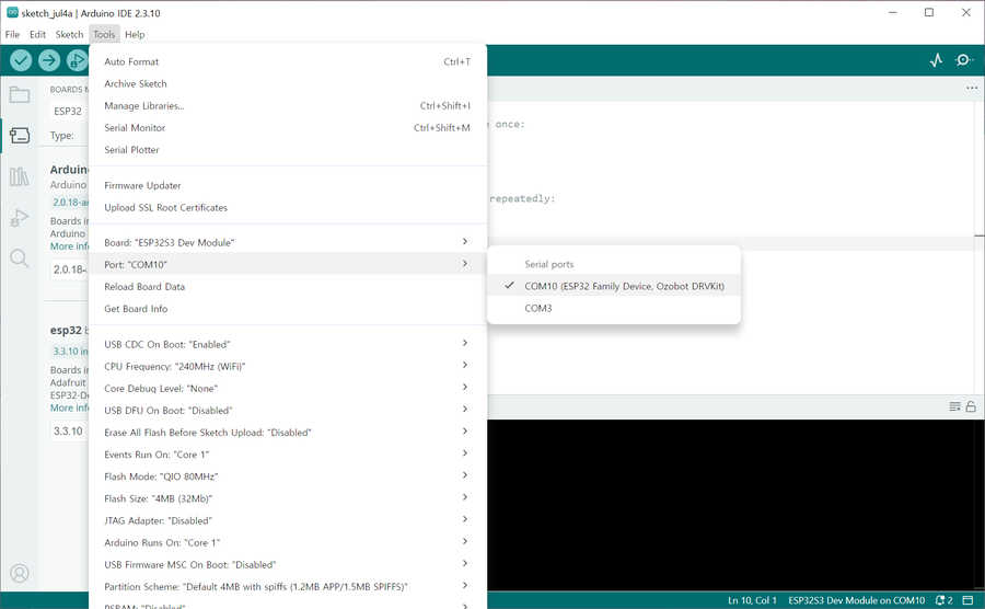
Tools → Port, then select the newly-appeared COM port (e.g. COM10).
▲ Selecting the ESP32's COM port under Tools → Port
Port not showing up?
Try re-plugging the USB cable and clicking into the IDE window to refresh. Also confirm your cable actually supports data (a charge-only cable won't work).
Chapter 5
Blink Test — Your First Upload
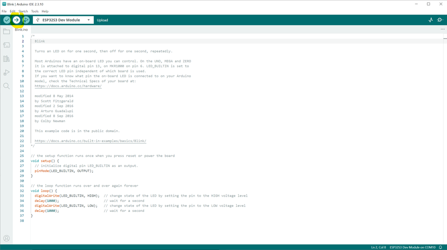
Once the board is configured, the first thing to do is upload Blink. It's a trivial LED-blinking sketch, but succeeding at this step proves in one shot that the hardware, driver, board settings, and upload path are all working correctly.
The Geekble Nano's built-in LED pin
The silkscreen on the back of the Geekble Nano marks D13 = GPIO48 as the built-in LED. The default Blink example (LED_BUILTIN) may not point to the right pin, so it's safer to specify it explicitly, as in the code below.
▲ Upload in progress — progress is shown in the log at the bottom
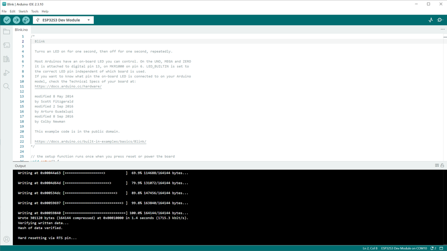
▲ Upload complete — the Hard resetting via RTS pin... message means success
Example success message: Wrote 301120 bytes ... in 1.4 seconds Hash of data verified. Hard resetting via RTS pin...
If the upload fails (common on the ESP32-S3)
The ESP32-S3 sometimes needs to be put into bootloader mode manually before it will accept an upload. Try these in order.
Method 1: click Upload → when Connecting... appears at the bottom, hold down the BOOT button → release once the upload starts
Method 2: hold BOOT → tap RST once → keep holding BOOT → click Upload
Checking the result
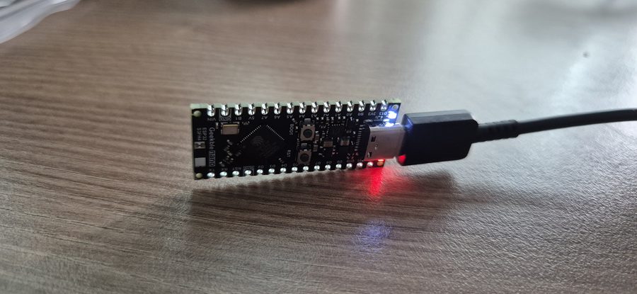
▲ The built-in LED (GPIO48) blinking every 0.5 seconds 🎉
If the LED blinks every 0.5 seconds, you're good. This confirms that the hardware, driver, board settings, and upload path are all working correctly, and you're ready to move on to implementing USB HID.
Chapter 6
Implementing a USB HID Keyboard
Now for the core of this project: implementing a USB HID Keyboard. The ESP32-S3 will be recognized by the PC as a USB keyboard, and code will be able to send keystrokes to it.
Step 1 — Check the USB settings
First, check the current USB-related settings in the Tools menu.
▲ Checking USB-related settings in the Tools menu
The key settings to check are:
Item
Setting
Board
ESP32S3 Dev Module
USB CDC On Boot
Enabled (needs to be changed)
USB Mode
Hardware CDC and JTAG
Flash Size
4MB
Step 2 — USB CDC On Boot → Enabled
Change Tools → USB CDC On Boot → Enabled.
This setting must be on for the USB device to initialize automatically after boot.
▲ USB CDC On Boot switched to Enabled
USB HID on Arduino ESP32 3.x
Starting with ESP32 Arduino Core 3.x, you can implement USB HID easily with the built-in USB.h + USBHIDKeyboard.h libraries — no separate TinyUSB install needed.
Step 3 — Write and upload the code
Create a new sketch, paste in the code below, and upload it.
#include "USB.h" #include "USBHIDKeyboard.h"
USBHIDKeyboard Keyboard;
void setup() { USB.begin(); Keyboard.begin();
// Wait for USB to be recognized delay(3000);
Keyboard.println("Hello World!"); Keyboard.println("ESP32-S3 USB HID Keyboard Test"); }
void loop() { }
▲ Writing and uploading the USB HID Keyboard sketch
Step 4 — Confirm the PC recognizes the USB keyboard
After uploading, confirm the PC recognizes the ESP32-S3 as a USB HID Keyboard device. You can check this in Windows Device Manager or via a notification.
▲ The PC recognizing the ESP32-S3 as a USB HID Keyboard device
Step 5 — Notepad typing test
Open Notepad, click into it to place the cursor, then press the ESP32's RST button once. If text types itself in after about 3 seconds, it worked.
▲ "Hello World!" and "ESP32-S3 USB HID Keyboard Test" typed automatically into Notepad 🎉
How it works USB.begin() → initializes the USB stack Keyboard.begin() → registers the HID keyboard device delay(3000) → waits for the PC to recognize the device Keyboard.println() → sends the keystrokes (including Enter)
This confirms the ESP32-S3 really does behave like a USB keyboard. The next step is adding Wi-Fi so this keystroke can be triggered remotely.
Chapter 7
Connecting to Wi-Fi
With USB HID confirmed working, it's time to connect to Wi-Fi. The goal of this step is simply for the ESP32-S3 to join the router and get an IP address.
Watch the init order when using USB HID + Wi-Fi together
On Arduino ESP32 Core 3.x, the initialization order matters when using USB and Wi-Fi together.
Verified order: Keyboard.begin() → USB.begin() → WiFi.begin() → server.begin()
while (WiFi.status() != WL_CONNECTED) { delay(500); }
// Connected — check the IP // Serial.println(WiFi.localIP()); }
void loop() { }
Checking the IP from the router
Once the ESP32 joins the router, it gets an IP via DHCP. Check the connected-devices list on the router's admin page, or print WiFi.localIP() to the Serial Monitor.
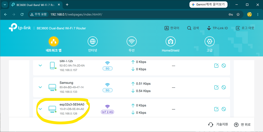
▲ Checking the ESP32's IP address on the router's admin page
▲ Checking Wi-Fi connection status and IP address in the Serial Monitor
Port-recovery tip (a common ESP32-S3 quirk)
While running in USB HID mode, the COM port can disappear. Don't panic — recover it by holding BOOT → RST → keep holding BOOT → Upload.
▲ The COM port disappearing, and recovering it with the BOOT button
Chapter 8
Building the HTTP Web Server
With Wi-Fi confirmed working, it's time to bring up an HTTP web server. This lets a phone or remote PC's browser send an HTTP request to the ESP32.
Opening http://[ESP32's IP address]/ in a browser shows a page served by the ESP32.
▲ Successfully connecting to the ESP32's web server in a browser
mDNS setup (optional)
Adding #include <ESPmDNS.h> and MDNS.begin("esp32") lets you connect via http://esp32.local/ instead of the IP address. This only works on the same Wi-Fi network.
Chapter 9
Final Code & Stabilization Work
The combined Wi-Fi + USB HID code wasn't stable right out of the gate. It worked, but USB recognition kept dropping and the keyboard behaved erratically. Here's the process of tracking down the causes, one by one, documented as it actually happened.
Bugs found and the root cause of the instability
The core bug: setTxPower was never actually being applied
Calling WiFi.setTxPower() before WiFi.begin() gets silently ignored, because the Wi-Fi driver hasn't started yet. So while I thought I was limiting output to 8.5dBm, it was actually transmitting at full power (~20dBm) the whole time. The current spike of 300mA+ during Wi-Fi transmission was colliding with USB enumeration timing — that was the root cause of the instability.
Six Stabilization Fixes
Item
Change
Effect
① setTxPower placement
Moved after WiFi.begin()
The 8.5dBm limit now actually takes effect — the single biggest fix
② USB init order
USB first → wait for tud_mounted() → then Wi-Fi
Separates things so the Wi-Fi current spike happens after USB enumeration finishes
③ CPU clock
240MHz → 160MHz
Still plenty of performance, with more headroom for current spikes
④ Wi-Fi modem sleep
WiFi.setSleep(true)
Radio sleeps when idle → big drop in average current draw
⑤ loop() delay
Added delay(2)
Gives the CPU idle time so modem sleep can actually kick in
⑥ Declare Remote Wakeup
USB.usbAttributes(...REMOTE_WAKEUP)
Declares it in the USB descriptor → creates the Windows power-management tab
Setting the USB Remote Wakeup descriptor
For the Power Management tab to appear in Windows Device Manager, Remote Wakeup support must be declared in the USB descriptor. This one line has to be called before USB.begin().
// Must be called before USB.begin() USB.usbAttributes(TUSB_DESC_CONFIG_ATT_SELF_POWERED | TUSB_DESC_CONFIG_ATT_REMOTE_WAKEUP);
What waiting for tud_mounted() means USB.begin() doesn't mean the PC recognizes it right away. You have to wait for the PC to enumerate the USB device and match a driver. Once tud_mounted() returns true, USB is fully recognized. Turn on Wi-Fi before that check passes, and the current spike lands right in the middle of enumeration.
void handleWake() { if (tud_suspended()) { tud_remote_wakeup(); // Send the USB Remote Wakeup signal delay(1000); // Wait for the host to resume the bus } Keyboard.press(KEY_LEFT_SHIFT); delay(100); Keyboard.release(KEY_LEFT_SHIFT); server.send(200, "text/plain", "Wake signal sent!"); }
void setup() { setCpuFrequencyMhz(160); // 240→160MHz: more headroom for current spikes
// Declare Remote Wakeup in the USB descriptor (must be before USB.begin()) USB.usbAttributes(TUSB_DESC_CONFIG_ATT_SELF_POWERED | TUSB_DESC_CONFIG_ATT_REMOTE_WAKEUP); Keyboard.begin(); USB.begin();
// Wait for USB enumeration to finish (up to 3s) uint32_t t0 = millis(); while (!tud_mounted() && millis() - t0 < 3000) delay(50); delay(500); // Extra settling time right after enumeration
WiFi.persistent(false); WiFi.setAutoReconnect(true); WiFi.mode(WIFI_STA); WiFi.begin(ssid, password); WiFi.setTxPower(WIFI_POWER_8_5dBm); // Must be called after begin() to actually apply WiFi.setSleep(true); // Modem sleep: lowers average current draw
void loop() { server.handleClient(); delay(2); // Gives modem sleep time to actually engage }
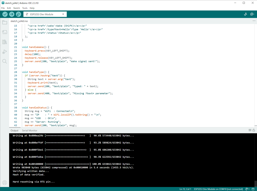
▲ Final code uploaded successfully — Wrote 983040 bytes, Hard resetting via RTS pin...
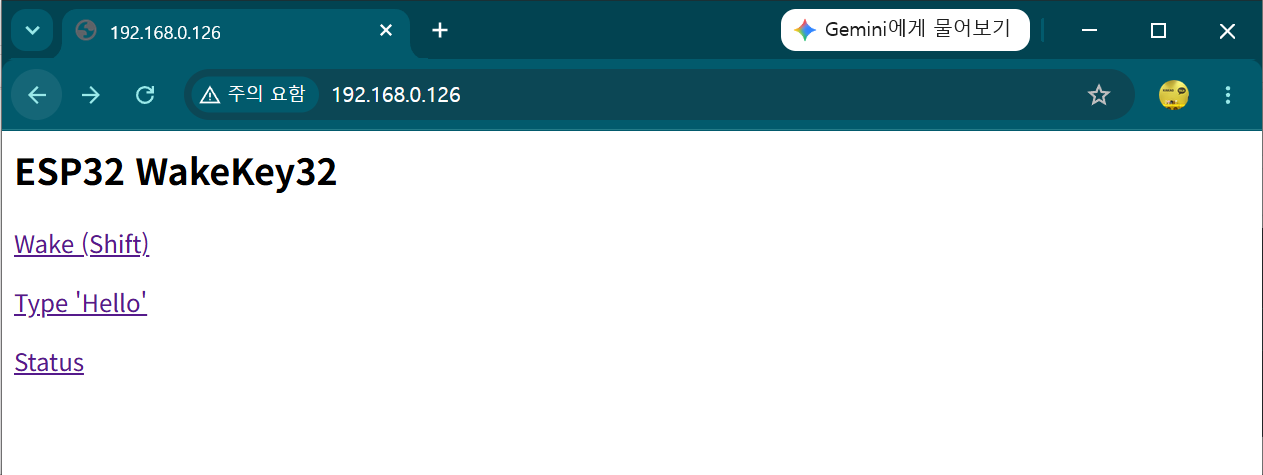
▲ The finished index page — Wake (Shift) / Type 'Hello' / Status, three endpoints reachable from here
▲ Result of calling /type?text=Hello — "Hello" typed automatically into Notepad
The /status diagnostic page
A diagnostic endpoint for checking status without a Serial connection. If USB recognition gets flaky, open http://[IP]/status.
WiFi : Connected IP : 192.168.0.xxx RSSI : -52 dBm USB : Mounted Reset : Power-on Uptime: 42 s
Reset: BROWNOUT (power drop!) means it's a power problem, not a code problem.
Switch to a rear USB port on the PC (motherboard-connected) or use a USB 3.0 port (900mA). If RSSI is worse than -75dBm, consider bumping up to WIFI_POWER_11dBm.
Troubleshooting
Troubleshooting — Real Issues I Ran Into
Here's a rundown of the issues I actually hit while building this, and how I fixed them. If you're new to the ESP32-S3, you'll likely run into every one of these at least once.
① The COM port disappears after uploading
Once it switches into USB HID mode, Windows recognizes the ESP32 as an HID keyboard rather than a serial port, so the COM port disappears.
Fix: enter bootloader mode in this order, then upload.
1. Hold down the BOOT button
2. Tap RST briefly and release
3. Release BOOT
4. Click Upload in Arduino IDE
If Serial Monitor shows waiting for download, you've successfully entered bootloader mode. From there, Upload works even without a COM port.
▲ Successfully uploading after entering bootloader mode
② It stops after "Hard resetting via RTS pin..."
If this message appears at the end of an upload, the upload succeeded. The ESP32 resets itself automatically and runs the new code. No action needed.
If it instead drops into a bootloader-wait state (waiting for download) after this message, just press RST once to boot normally.
③ Wi-Fi keeps connecting and dropping
The ESP32's Wi-Fi radio draws a momentary current spike (up to 500mA) when it powers on. If the PC's USB port can't supply enough power, the resulting voltage drop makes the connection unstable.
Fixes (in priority order):
1. Switch to a phone charger (5V 1A or higher) for power
2. Plug directly into the PC instead of through a USB hub
3. Add WiFi.setTxPower(WIFI_POWER_8_5dBm) in code to lower transmit power
▲ Plugged directly into a PC USB port with a short cable, to minimize power loss
④ Nothing shows up in Serial Monitor
This happens when the output already scrolled by before you opened Serial Monitor. Open Serial Monitor first, then press RST to reboot — the output will start from the beginning. Also double-check the baud rate matches the code (115200).
⑤ USB HID conflicting with Serial (CDC)
With USB CDC On Boot: Enabled, calling both Serial.begin() and USB.begin() can make the port disappear or conflict.
Fix: when USB CDC On Boot: Enabled is set, Serial is already wired to the USB CDC port, so there's no need to call Serial.begin() separately. Calling both Serial.begin() and USB.begin() makes two initializations fight over the same USB port, which is what causes the COM port to disappear or become unstable. Serial.print() and friends work fine over USB CDC without any separate init.
⑥ USB HID + Wi-Fi initialization order problem
Calling USB.begin() before Wi-Fi can cause the USB FreeRTOS task to interfere with Wi-Fi stack initialization, preventing Wi-Fi from connecting.
A USB HID keystroke alone can't wake a sleeping PC. For a USB device to wake a PC from sleep, it has to separately send a Remote Wakeup signal over the USB bus — this is exactly why an ordinary wireless keyboard dongle is able to wake a PC from sleep.
Step 1 — Code change: add tud_remote_wakeup()
On Arduino ESP32 Core 3.x, USB.wakeupHost() doesn't exist. You have to use TinyUSB directly. Add #include "tusb.h" and send the signal with tud_remote_wakeup().
void handleWake() { if (tud_suspended()) { tud_remote_wakeup(); // Send the USB Remote Wakeup signal (the key part) } delay(500); // Wait for the PC to wake up Keyboard.press(KEY_LEFT_SHIFT); delay(100); Keyboard.release(KEY_LEFT_SHIFT); server.send(200, "text/plain", "Wake signal sent!"); }
How to confirm it's working: after the PC sleeps, if http://[IP]/status shows Suspended: Yes, USB is correctly in the suspended state. Calling /wake from there sends the Remote Wakeup signal.
Step 2 — Windows Device Manager setting
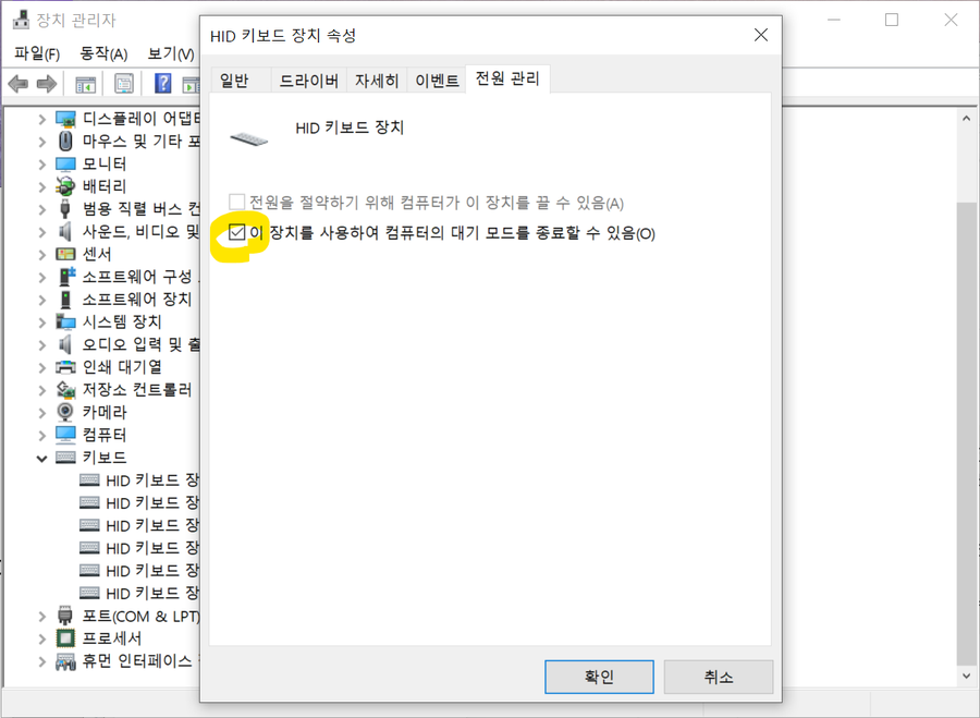
By default, Windows doesn't allow any USB device to wake the computer from sleep. You need to enable this for the ESP32 HID keyboard device ahead of time, while the PC is on.
You must configure this while the PC is powered on. It can't be set after the PC is already asleep.
1. Open Device Manager (Win+X → Device Manager)
2. Expand Human Interface Devices
3. Right-click the ESP32 HID Keyboard device → Properties
4. Power Management tab → check "Allow this device to wake the computer"
5. Click OK
I put the Windows PC to sleep, waited a while, then called it from a different PC using one of the methods below.
Three calling methods — all confirmed working
① Browser address bar: http://192.168.0.12/wake
② curl (terminal/command prompt): curl http://192.168.0.12/wake
③ Clicking from the index page: http://192.168.0.12/ → click the Wake (Shift) link
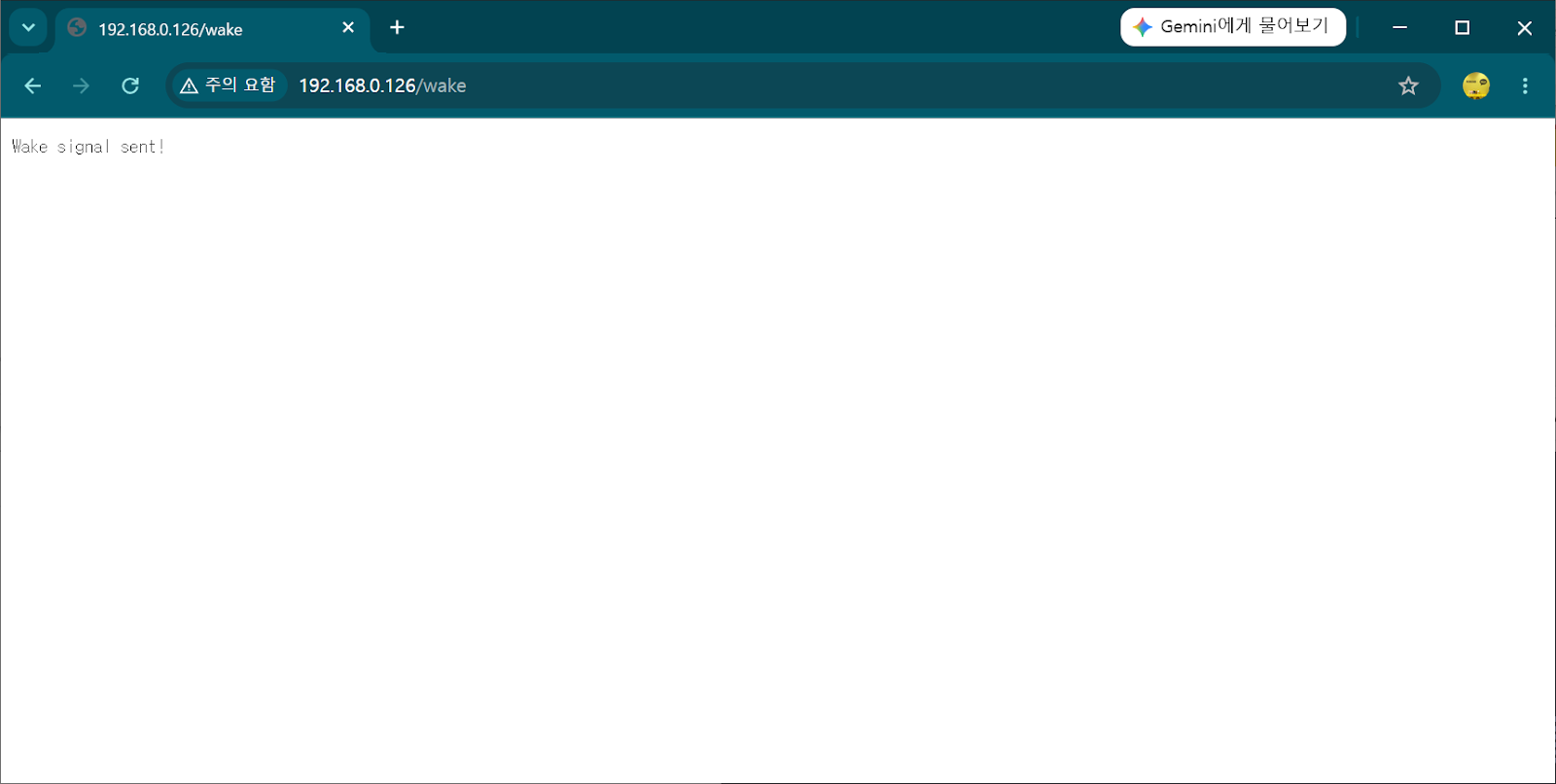
▲ Response to calling /wake — "Wake signal sent!" means the Remote Wakeup signal and Shift keystroke went through correctly
All three methods successfully woke the sleeping Windows PC. With that, this project's final goal was achieved.
Final confirmed flow
Another PC / phone browser
→ HTTP request to http://[ESP32 IP]/wake
→ ESP32 sends a USB Remote Wakeup signal via tud_remote_wakeup()
→ Windows wakes from sleep
→ Then connect remotely via RDP, etc. ✅
Download the Final Code
You can download this project's finished code (.ino) and use it as-is.
Before you download, you must edit this: the ssid and password values in the code are placeholders,
YOUR_WIFI_SSID / YOUR_WIFI_PASSWORD.
Replace them with your own router's SSID and password before uploading.
If you want to power on a desktop PC even from a full shutdown (BIOS setting included), check out Part 2, built on an AliExpress ESP32-S3 board. The code is 100% identical to this post.